Bipolar Plates Cooling Plates
Description
Contact us: [email protected]
WhatsApp: +8613355741031
Stack Thermal & Flow Field Solutions
Bipolar Plates + Ultra-Thin Cooling Plates for PEMFC, SOFC, AEM & Flow Battery Systems
1. Product Overview
One supplier. Two mission-critical components. One integrated thermal and flow field strategy.
This product page presents our complete hardware solution for fuel cell stacks and flow battery systems:
-
Bipolar Plates (BPP) – for reactant distribution, current collection, and cell separation
-
Ultra-Thin Cooling Plates – for precision thermal management with ΔT < 2°C across the active area
Designed for engineers who need reliable, repeatable, and scalable stack hardware – from R&D prototyping to high-volume production (500,000+ pieces/year).
Why buy them together?
Bipolar plates and cooling plates share the same manufacturing DNA (stamping, etching, brazing/welding, leak testing) and the same operating environment. Sourcing both from a single supplier eliminates interface mismatches, reduces supply chain complexity, and lowers total cost of ownership.
2. Key Benefits at a Glance
| Benefit | How We Deliver |
|---|---|
| Higher stack power density | Metal bipolar plates down to 0.05 mm; integrated cooling channels where needed |
| Longer stack lifetime | Corrosion-resistant coatings (Au, C, CrN) validated to 5,000+ hours AST; helium leak test ≤1×10⁻⁸ Pa·m³/s |
| Lower stack cost | High-volume stamping + in-house coating + automated sealing – no middle layers |
| Better thermal uniformity | Micro-channel cooling plates with flow-optimized geometry; ΔT ≤ 2°C across active area |
| Single point of responsibility | One supplier, one quality system, one logistics stream – for two tightly coupled components |
3. Product Series A – Bipolar Plates
3.1 Metallic Bipolar Plates (High-Volume, High-Power PEMFC)
Best for automotive, heavy-duty truck, and stationary high-power stacks
| Parameter | Specification |
|---|---|
| Materials | 316L, 310S, titanium (Grade 1/2), coated SS |
| Thickness | 0.05 – 0.10 mm |
| Channel depth tolerance | ±0.01 mm |
| Flatness | ≤0.02 mm over 200 mm length |
| Coating (in-house PVD) | Gold (≤50 nm), amorphous carbon (≤200 nm), CrN |
| ICR (after coating) | <5 mΩ·cm² @ 1.4 MPa |
| Corrosion current density | <1 μA/cm² (PEMFC cathode conditions) |
| Leak rate (helium) | ≤1×10⁻⁸ Pa·m³/s per plate |
| Integrated features | Cooling channels, sealing grooves, alignment pins |
| Joining method | Laser welding (two-piece plates) |
3.2 Graphite & Composite Bipolar Plates (Long-Life SOFC / Backup Power)
Best for high-corrosion environments and low-current-density applications
| Parameter | Specification |
|---|---|
| Materials | Natural/expanded graphite + phenolic resin, or pure molded graphite |
| Thickness | 0.8 – 1.2 mm (composite); 1.5 – 3.0 mm (pure graphite) |
| Flatness | ±0.02 mm |
| Porosity (after impregnation) | <1% – eliminates gas crossover |
| Corrosion resistance | Inherent – no coating required |
| Manufacturing | Compression molding or high-speed CNC milling |
3.3 Ultra-Thin Plates for Maximum Power Density
| Material | Thickness | Benefit |
|---|---|---|
| Metal | 0.05 – 0.08 mm | Reduces stack volume by up to 30% |
| Composite | 0.8 – 1.2 mm | Fiber-reinforced for mechanical strength |
| Surface finish | Ra ≤0.4 μm | Minimizes contact resistance with GDL |
3.4 Custom Flow Field Designs
We help you optimize the trade-off between pressure drop and water removal:
-
Serpentine (1-, 2-, or 3-pass)
-
Parallel & interdigitated
-
Pin-type & 3D meshed
-
Bio-inspired (leaf vein, lung-like)
Flow fields can be machined, stamped, or etched – depending on volume and material.
4. Product Series B – Ultra-Thin Cooling Plates
4.1 Why Cooling Plates Are Essential
A fuel cell operates at 60–80°C. Exceeding this range causes:
-
Membrane dehydration → performance collapse
-
Hot spots → accelerated degradation
-
Thermal runaway → catastrophic failure
Cooling plates maintain ΔT < 2°C across the entire active area – enabling stable, long-life operation.
4.2 Cooling Plate Product Line
| Cooling Plate Type | Application | Material | Channel Design | Bonding Method |
|---|---|---|---|---|
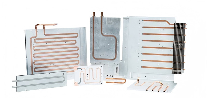
| Micro-channel cold plates | PEMFC stacks, dense heat load | 316L, Ti, Al 6061 | Serpentine or parallel micro-channels (0.3–0.8 mm hydraulic diameter) | Vacuum brazing / diffusion bonding |
| Liquid cooling jackets | Battery packs, PCS, power electronics | Aluminum (brazed) | Large cross-section, low pressure drop | Controlled atmosphere brazing (CAB) |
| Integrated BPP + cooling plate | Ultra-compact stacks | 316L, Ti | Cooling channels machined directly on backside of bipolar plate | One-piece forming + laser welding |
4.3 Cooling Plate Key Specifications
| Parameter | Value |
|---|---|
| Thickness (standalone cooling plate) | 0.6 – 1.5 mm |
| Channel depth tolerance | ±0.01 mm |
| Hydraulic diameter (micro-channel) | 0.3 – 0.8 mm |
| Pressure drop (typical) | <50 kPa @ 2 L/min coolant flow |
| Helium leak rate | ≤1×10⁻⁸ Pa·m³/s |
| Coolant compatibility | Deionized water / water-glycol (up to 50/50 mix) |
| Burst pressure | ≥1.5 MPa |
| Thermal uniformity (ΔT across active area) | ≤2°C |
4.4 Cooling Plate Manufacturing Technologies
| Process | Advantage for Cooling Plates |
|---|---|
| Precision stamping (micro-channels) | High-volume, low-cost, 0.1 mm channel width capability |
| Chemical etching | Burr-free, stress-free – ideal for R&D and complex geometries |
| Vacuum brazing | Clean, oxide-free joints – no post-braze cleaning required |
| Diffusion bonding | Monolithic structure, no braze filler – maximum reliability |
| Laser welding | Hermetic sealing of two-piece cooling plate assemblies |
.jpg)
5. Quality Assurance & Testing
All plates – both bipolar and cooling – undergo 100% testing on critical parameters.
| Test | Method | Acceptance Criteria |
|---|---|---|
| ICR (Interfacial Contact Resistance) | 4-probe method @ 1.4 MPa | <5–10 mΩ·cm² |
| Corrosion current density | Potentiodynamic scan (0.6V vs. SCE, 80°C, 0.5M H₂SO₄+2 ppm HF) | <1 μA/cm² |
| Helium leak test | Mass spectrometry | ≤1×10⁻⁸ Pa·m³/s per plate |
| Flatness | CMM / optical flat | ≤0.02 mm over 200 mm |
| Channel depth | Laser profilometer | ±0.01 mm |
| Salt spray (coated metal plates) | ASTM B117 | ≥500 hours |
| Thermal uniformity (cooling plates) | IR thermography | ΔT ≤2°C across active area |
| Pressure cycling (cooling plates) | 0–0.5 MPa cyclic, 10,000 cycles | No leak, no deformation |
Certifications
-
ISO 9001:2015
-
IATF 16949 (automotive-grade fuel cell quality systems)
-
Customer-specific audits (VDA 6.3, etc.)
Manufacturing Capabilities – At a Glance
| Process | Key Capability |
|---|---|
| Precision stamping (progressive die) | 0.05 mm SS, ±0.01 mm channel depth, up to 120 strokes/min |
| Chemical etching | Burr-free, complex micro-channels, no mechanical stress |
| MIM (Metal Injection Molding) | Small, complex composite plates and manifolds |
| 5-axis CNC machining | Graphite plates, R&D prototypes, complex flow fields |
| Compression molding | Composite plates with thermoset resins + graphite fillers |
| Laser welding | Hermetic sealing of two-piece plates |
| Vacuum brazing / diffusion bonding | Clean, high-integrity cooling plate joints |
| Coating (in-house PVD) | Gold, carbon, CrN – ICR stability & corrosion protection ≥5,000h AST |
| Sealing (automated) | Silicone or EPDM gaskets – dispensed, hot-bonded, or screen-printed |
| Cleanroom final cleaning | Class 10K, DI water + ultrasonic – residue <0.1 mg/cm² |
Applications
| Application | Bipolar Plate Recommendation | Cooling Plate Recommendation |
|---|---|---|
| Automotive PEMFC (cars, SUVs) | Metallic, 0.075 mm, coated | Micro-channel, 0.8 mm, vacuum brazed |
| Heavy-duty truck fuel cell | Metallic, 0.10 mm, reinforced coating | Micro-channel with higher burst pressure |
| Stationary power (PEMFC) | Metallic or composite – depending on lifetime requirement | Standard micro-channel cooling plate |
| SOFC (high-temperature) | Graphite or composite | High-temp compatible materials (e.g., special alloys) |
| Flow battery (vanadium redox) | Graphite or carbon-polymer composite | Corrosion-resistant cooling / thermal management plates |
| R&D / university stacks | Any – custom flow fields, small quantities | Any – custom cooling channel geometries |
Get in Touch with Yichou
- Email us: [email protected]
- Call us/whatsapp: +86 13355741031
- Chat with us: Live chat support available on our website
People who viewed this item also viewed