Abstract:In order to meet engineering requirement of the silicon carbide materials parts,the machining property of SiC parts was studied.First,the material properties of SiC was analyzed;then,the experiments of the grinding technology, CNC machining,linear cutting and ultrasonic machining were carried out according to the material properties of SiC;Fin ally,to solve some problems in the process,the countermeasures were puted forward.Experimental results show that the engineering demand could be met using grinding.process methods with aluminum alloy composites diamond grinding wheel and good results were obtained.
Key words:SiC materials;machining property;diamond grinding wheel
The new material silicon carbide ( SiC ) has a series of excellent physical and chemical properties such as high specific stiffness, good thermal stability and light weight. Researchers around the world have listed it as the preferred mirror material for space optical remote sensors [ 1-2 ]. With the rapid development of science and technology, silicon carbide material is the most rapid development of materials. A new army has begun to be used in engine combustion parts, rocket nozzles, gas turbine engine blades, gates for pouring metals, heat exchange materials for thermocouple sleeves at high temperatures, and encapsulation materials for nuclear fuels in many industrial fields such as automotive, mechanical, aerospace, chemical, and petroleum.
The United States, Russia, Germany, France, and other countries have been researching SiC materials since the early 1980s. In the 1990s, SiC was used to make mirrors and applied in optical systems with large temperature changes [5-7]. China's research on SiC materials is basically synchronized with the international level, and optical processing technology is relatively mature, while there are relatively few reports on mechanical processing. Due to the increasing application of silicon carbide materials in the mechanical industry, relying solely on sintering casting to ensure dimensional accuracy and positional tolerances not only increases the difficulty of casting, but also reduces the accuracy of tolerance fitting. In response to the characteristics of high hardness and difficulty in ordinary mechanical processing of silicon carbide, this article conducted research on the machining process method of silicon carbide and achieved good experimental results.
1 Properties of silicon carbide materials
Reaction sintering method, also known as self bonding method or silicon infiltration method, is a method of mixing and pressing - SiC and graphite in a certain proportion to form a green body, heating it to around 1650 ℃, and penetrating Si into the green body through liquid or gas phase to react with graphite to produce - SiC. At the same time, the original - SiC particles are combined to achieve densification. The sintered body contains 8% to 10% free silicon, and reaction sintering is usually completed by induction heating a graphite crucible under vacuum.
Due to the principle of silicon carbide reaction sintering, SiC has many excellent characteristics that other materials do not have [ 8-10 ] : ( 1 ) The specific stiffness is large, the deformation of the structure caused by the unit load is small, the dimensional stability is good, and the thickness of the mirror can be reduced. The honeycomb structure is made to reduce the weight, and the mirror and the frame are integrated to reduce the adjustment error. ( 2 ) The thermal deformation coefficient is small and the thermal shock resistance is superior, which can make the mirror body have good thermal stability in a wide temperature range, reduce the requirements of the thermal control system, and reduce the quality and power consumption of the thermal control system. ( 3 ) Good thermal conductivity. When the ambient temperature changes, the material is easy to achieve internal temperature balance, will not cause a lot of internal stress, strong ability to adapt to the environment, long service life.
2 Processing technology of silicon carbide mechanical parts
The parts of the same structure can be processed by ordinary lathe workers and milling workers, but Si C mechanical parts cannot be processed. Special processing methods such as grinding, CNC machining, EDM and ultrasonic machining are needed. Due to the hardness of the material, ordinary tools are difficult to cut, so special tools are used.
2.1 Grinding process
2.1.1 Precision grinding
Taking the silicon carbide parts shown in figure 1 as an example, the grinding process method is analyzed. The upper and lower surfaces are to be processed. The flatness of the upper surface is 0.008 mm, and the upper and lower surfaces are parallel 0.01 mm. Such as aluminum or steel parts, process design generally adopts milling or planing processing method, tolerance is easy to achieve ; for the processing of the three holes in Fig.1 ( shown in Fig.3 ), it is usually convenient to use lathe workers or boring workers. However, for silicon carbide parts, the above several process methods are difficult to achieve, and only unconventional grinding can be used.
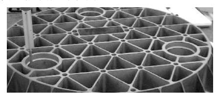
Fig.1 Photo of the Sic mirror
Due to the high hardness and difficulty in machining of the material, a precision grinding machine (MG7132) with high stiffness and good system feed was selected for process testing, with a feed accuracy of less than 5 meters. Firstly, a 250 * 32 aluminum based resin bonded diamond grinding wheel was designed, with a grinding tool size of 60 # to 120 # and a concentration of 100% to 150%, with excellent performance. Additionally, an excellent grinding coolant was purchased. Due to the sufficient machining allowance of the parts, necessary conditions are provided for grinding experiments. Firstly, experiments were conducted on feed rate and surface roughness, and the results are shown in Figure 2.
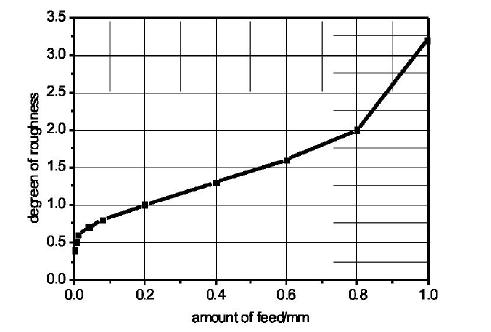
Fig.2 The relationship curve of feeding and surface roughness
It can be concluded from Fig.2 that the smaller the feed rate of the machine tool, the better the surface roughness and the higher the surface accuracy. In the process of machining, the appropriate feed rate can be selected according to the surface roughness to be achieved.
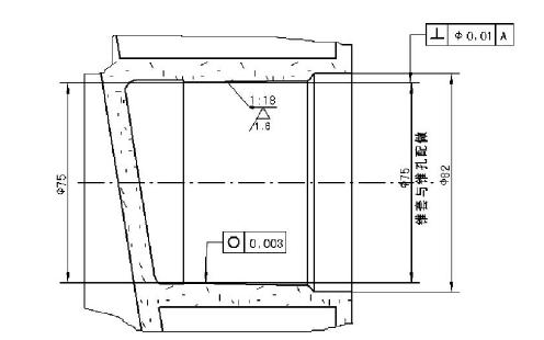
Fig.3 Dimensional tolerance and geometrical tolerance of holes of Sic mirror
In the grinding process, even if the surface roughness is low, but the amount of each cutting can not be too large, there must be a limit.
Maximum cutting thickness:

In the formula : vc-the speed of the grinding wheel ( m / s ) ; vw - the speed of the workpiece ( m / s ) ; fr - radial feed ( mm ) ; the diameter of do-grinding wheel ( mm ) ; e - Grinding wheel granularity number.
According to the formula, it can be seen that the cutting amount is related to the grinding wheel speed, diameter and particle size, workpiece speed and feed rate. When h is too large, the grinding wheel will suddenly stop grinding, resulting in too much local removal of the workpiece, and the surface will be sunken, resulting in the scrapping of the workpiece. Therefore, the maximum cutting amount must be strictly controlled. After repeated experiments, when grinding silicon carbide material parts, the grinding speed is generally 20m / s, the feed rate is 2mm / min, and the maximum grinding thickness is 0.1mm. The process parameters can obtain a relatively smooth, smooth and shiny surface. The actual size and shape and position tolerances after processing are measured by three-coordinate detection as shown in Tables 1 and 2 below.All meet the engineering requirements.
Tab.1 The theoretical and measured value of the surface
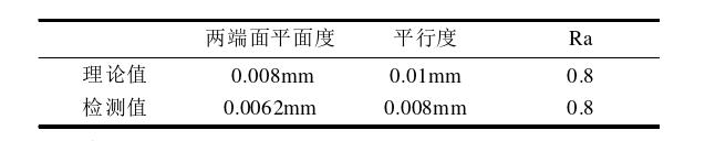
Tab.2 The theoretical and measured value of the hole

The problem in the experiment : when the machining allowance is less than 0.5mm, there are many fine edge collapses at the edge of the grinding process, and the cutting force of the grinding wheel decreases significantly. After analysis, the process measures taken are as follows : when the allowance is 0.5 mm, it is first poured into a blunt angle ; in addition, the silicon carbide coarse grinding wheel is used to dress the diamond fine grinding wheel, and the cooling water is used to brush it, which can effectively prevent the edge collapse.
2.1.2 CNC grinding
CNC machining integrates machining and digital control. It mainly relies on programming to control turning tools or milling cutters to process some curves or irregular curves. At present, for the grinding machine, the numerical control grinding machine can not be processed as shown in Fig.4, and the feed accuracy and machine speed are controlled by computer program. At present, there is no grinding part size like CNC milling. Under the condition that the project is in urgent need of processing, the numerical control milling machine is reformed. Without changing the numerical control programming, the milling tool holder can be transformed into a device that can be loaded with grinding wheels, and the complex dimensions of some silicon carbide parts can be programmed and processed. According to the characteristics of CNC machining, the grinding wheels are designed : 60 * 8,60 * 16 aluminum resin bonded diamond grinding wheels, particle size 60 # ~ 80 #, concentration 120 %. After a large number of tests, the processing parameters of grinding line speed 20m / s, grinding feed 0.01mm, feed 4mm and feed 2m / min can meet the engineering requirements.
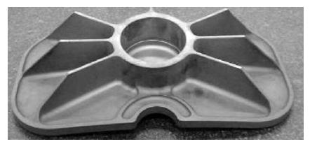
Fig.4 Photo of the silicon carbide part
The problem encountered in the experiment is that due to the high hardness of silicon carbide, the grinding wheel is severely worn, and the grinding particles of silicon carbide grind with the machine tool guide rail, which greatly damages the accuracy of the machine tool. The use of the machine tool guide rail protection device cannot effectively protect it. Due to the significant environmental pollution caused by the injection of coolant, there is currently no good solution, and further research is needed.
2.2 Wire Cut EDM Machining
Wire electrical discharge machining ( WEDM ) is to perform pulse discharge machining on the workpiece through the relative motion of the tool electrode and the workpiece electrode. The electrode wire moves relative to the workpiece at a certain speed in its axial direction and sprays the working fluid between the electrode wire and the workpiece slit. Combined with the different sintering methods of silicon carbide, high-purity SiC has high resistivity ( insulator ) and cannot be machined by wire cutting. When there are only impurities such as iron ions, the resistivity is reduced to about 1 ohm, especially the existence of free silicon ( some materials have 8 % ~ 10 % free metal Si ), which improves the conductivity of silicon carbide and provides the necessary conditions for EDM.Slow wire cutting ( the advantages of stable and non-vibration, low loss, high machining accuracy and low surface roughness ) is used for machining experiments.
The process measures adopted are as follows : increasing the current, placing silver foil on the contact surface between silicon carbide and workbench and the bottom of the pressure plate, strengthening the conductivity and putting some silver powder in the coolant to force the conductivity. Through a large number of experiments, the size of the workpiece in Fig.4 is machined by wire cutting, which can also meet the engineering requirements ( the premise material is micro-conductive ).
2.3 Ultrasonic CNC Machining
Ultrasonic machining can process various conductors, semiconductors, non-conductor materials, metal materials and non-metallic materials. For some insulating silicon carbide materials, wire cutting cannot be used. In addition to the use of CNC machine tools to transform grinding, ultrasonic machining can be used. 1-ultrasonic generator ; 2-cooling water inlet ; 3-transducer.
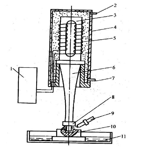
- ultrasonic generator ; 2 - cooling water inlet ; 3-transducer ; 4 - Outer cover ; 5 - circulating cooling water ; 6 - amplitude transformer ; 7 - Cooling water outlet ; 8 - Tools ; 9-working fluid ( abrasive suspension ) ; 10 - Workpiece; 11 - Work slot
Fig.5 Basic principle of ultrasonic machining
The basic principle of ultrasonic machining [12] is shown in Figure 5, which uses the tool surface 8 for ultrasonic vibration and the abrasive suspension 9 between the tool and the workpiece for mechanical processing. When loading, the tool is lightly pressed onto the workpiece, and liquid suspensions such as abrasive and water or kerosene are added between the workpiece and the tool. When the ultrasonic transducer generates axial vibration with a frequency of over 16000Hz, the amplitude is amplified to 0.05-0.0mm through a variable amplitude rod, driving the end face of the tool to undergo axial ultrasonic vibration, continuously impacting and polishing the machined surface with suspended abrasive particles in the impact working fluid at a high speed and acceleration, Causes the material to crack, break, and be crushed into very fine particles for separation. At the same time, the working fluid is subjected to ultrasonic vibration on the tool end face, generating high-frequency and alternating hydraulic positive and negative shock waves, which promote the working fluid to penetrate into the micro cracks of the processed material, exacerbating the destructive effect.
The main factors affecting the accuracy of ultrasonic machining are machining size and part shape, machining depth, processed materials, tool accuracy and vibration size, abrasive particle size and the accuracy of machine tools and fixtures. The accuracy is generally ± 0.02 ~ ± 0.05 mm. The relationship between machining accuracy and abrasive particle size is the largest. The smaller the abrasive particles, the higher the machining accuracy.
The ultrasonic machining process parameters of silicon carbide material are as follows : silicon carbide abrasive is used, kerosene is mixed with abrasive, and ultrasonic rotary machining is used to process holes. The surface roughness is Ra 0.8 ~ 1.6 m, which meets the requirements of design drawings. However, the processing cost is expensive, the processing time is long, the tool setting is difficult, and the local edge is broken, which needs further research.
3 Conclusion
By analyzing the performance of SiC materials and studying the mechanical processing technology of parts, suitable mechanical processing methods and parameters for silicon carbide materials are explored. This article mainly introduces the transformation of CNC machine tools into independently developed machine tools suitable for silicon carbide grinding and the design results of specialized grinding wheels. Based on the characteristics of silicon carbide materials, research has been conducted on wire cutting and ultrasonic machining technologies. In summary, a set of scientific, standardized, and efficient mechanical processing technology experiences for silicon carbide components have been summarized through experiments, providing a reliable technical foundation for precision mechanical processing of silicon carbide materials in the future.
-
FAQ: What are the advantages of machining silicon carbide parts for advanced applications? Answer: Machining silicon carbide parts offers several advantages, including exceptional hardness, thermal stability, and chemical resistance. These properties make them ideal for demanding applications in industries such as aerospace, automotive, and electronics, where high-performance components are required.
-
FAQ: How does YICHOU ensure the quality of its silicon carbide parts during the machining process? Answer: At YICHOU, we prioritize quality by employing advanced machining techniques and state-of-the-art equipment. Our skilled technicians and stringent quality control measures guarantee precision and consistency in manufacturing silicon carbide parts, ensuring they meet the exact specifications and performance requirements of our customers.
-
FAQ: Can YICHOU customize silicon carbide parts for specific applications? Answer: Yes, absolutely! At YICHOU, we understand that different industries have unique requirements. We offer customized solutions for silicon carbide parts, tailoring their dimensions, shapes, and tolerances to suit specific applications. Our engineering team collaborates closely with clients to design and deliver parts that perfectly fit their needs.
-
FAQ: What are the key considerations for selecting a reliable silicon carbide parts manufacturer? Answer: When choosing a silicon carbide parts manufacturer, consider factors such as experience and expertise in machining these complex materials, adherence to industry standards and certifications, a proven track record of delivering high-quality products, and the ability to handle large-scale production while meeting deadlines.
-
FAQ: How can I request a quote for silicon carbide parts from YICHOU? Answer: Requesting a quote for silicon carbide parts from YICHOU is easy! Simply visit our website or contact our sales team via email or phone. Provide us with the necessary details, such as part specifications, quantities, and any customization requirements. Our team will promptly get back to you with a competitive quote and further assistance.
How to Contact Us:
- Visit our website: https://www.nbyichou.com/
- Email us: [email protected]
- Call us/whatsapp: +86 13355741031
- Chat with us: Live chat support available on our website