Abstract : This paper introduces the application of OKUMA gantry pentahedron CNC machining center in the processing of large parts. Taking the processing of drawing die punch as an example, the process strategy of three-dimensional machining of large parts is expounded. In view of the particularity of the equipment, this paper introduces how to use UG software to realize the three-dimensional machining programming of OKUMA pentahedron, and discusses the difficulties and treatment methods in programming.
Keywords : OKUMA pentahedron machining center ; large parts ; UG software ; three-dimensional programming
As a high, fine and sharp equipment, the pentahedral CNC machining center is more and more widely used in enterprises, especially for the processing of large parts, which has great advantages. The three-dimensional processing of pentahedron is also an extremely important processing mode in modern automatic programming processing. It plays an important role in processing various parts of large and complex surfaces. However, the pentahedron three-dimensional programming is quite different from the vertical and horizontal machining center programming. When using the horizontal milling head for processing, it is necessary to comprehensively consider the operability of the machine tool, CNC system and software programming.
This paper will introduce the application of OKUMA pentahedron. Taking the processing of the convex die of the drawing die of the shell as an example, this paper expounds the processing technology strategy of large parts on the equipment, discusses how to use UG software to realize the numerical control programming of pentahedron, and discusses the programming difficulties and corresponding treatment methods.
1 OKUMA Pentahedral Gantry Machining Center Introduction
As shown in Figure 1 and Figure 2, the bed, column and top beam of the machine tool constitute a closed gantry structure. The beam can be lifted and lowered on the column, and the spindle head is hung on the beam. The 350 mm × 350 mm ram is fed in Z direction with a stroke of 650 mm. The worktable and the beam guide rail are all composed of rolling and sliding composite structures, and the mounted motor is adopted. The spindle speed is 6 000 r / min. The standard is vertical and horizontal two additional heads, so the area is small and the cost performance is high. The pentahedron machining center can complete the processing of multiple surfaces after one clamping, that is, after one clamping of the workpiece, the five surfaces except the bottom surface are processed, which has the functions of both vertical machining center and horizontal machining center. The position tolerance of the workpiece can be guaranteed during the machining process, and the dimensional consistency is good.
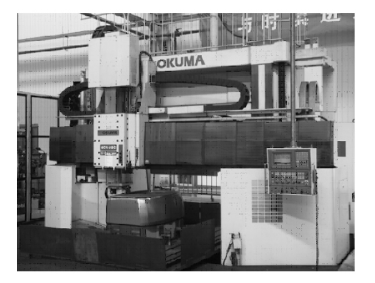
Fig.1 Vertical machining Fig.2 Horizontal machining
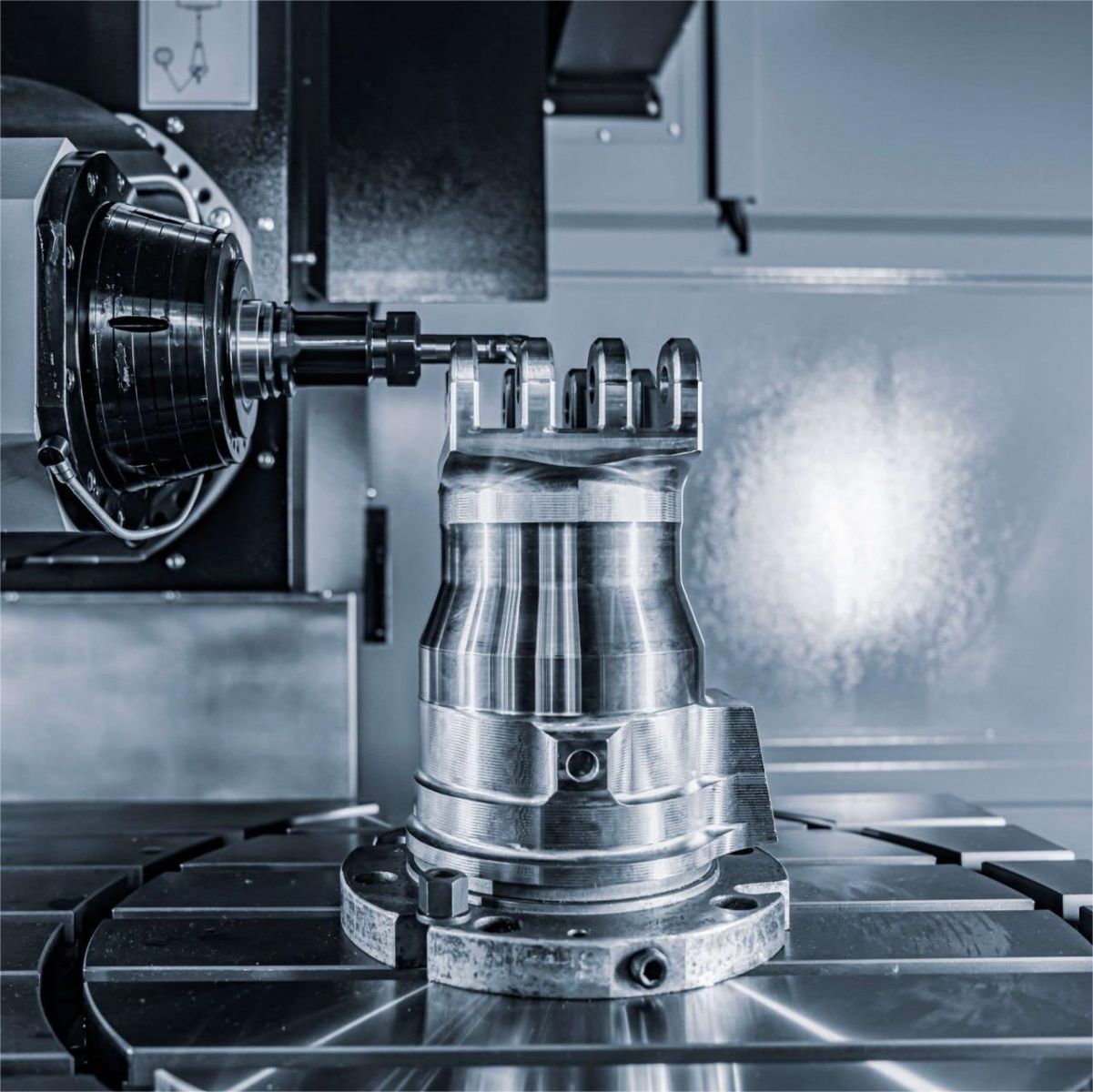
2 The application of pentahedron in the processing of shell punch
As shown in figure 3, the peripheral dimension of the shell punch is 2 300 mm × 2 100 mm, and the height is 800 mm. It is divided into two parts : the base and the forming body. The height of the forming body is about 700 mm, and the working surface is a complex surface. The rounded angle of the root of the pressure bar shown in the diagram is R3 mm. On the general vertical and horizontal machining centers, multiple clamping is required, and an auxiliary machining datum needs to be processed to complete the processing. However, the cutter marks of the three-dimensional machining of multiple clamping are obvious, and it is difficult to ensure the position and dimensional tolerance requirements of the machining. The part is processed on the pentahedron. Firstly, the size of the surrounding of the forming body relative to the center of the base is measured, and the approximate size and blank machining allowance are determined. According to the drawings and process requirements, the rough datum is marked and the numerical control center is established according to the principle of equal division of allowance, that is, the three-dimensional machining programming center. Once this center is established, it will remain unchanged until all the parts are processed and removed from the machine tool. After the parts are clamped, two or four reference holes should be processed in the appropriate position for standby, and then the guide plate mounting surface should be processed, and finally the three-dimensional processing of the working surface should be arranged. In the face of using UG software to program and process the working type, it is necessary to set the general processing boundary to pursue high efficiency and avoid excessive repeated processing range in local area.
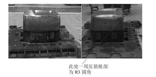
Fig. 3 Illustration of shell punch after processing
Process arrangement and key points to pay attention to for working surface processing:
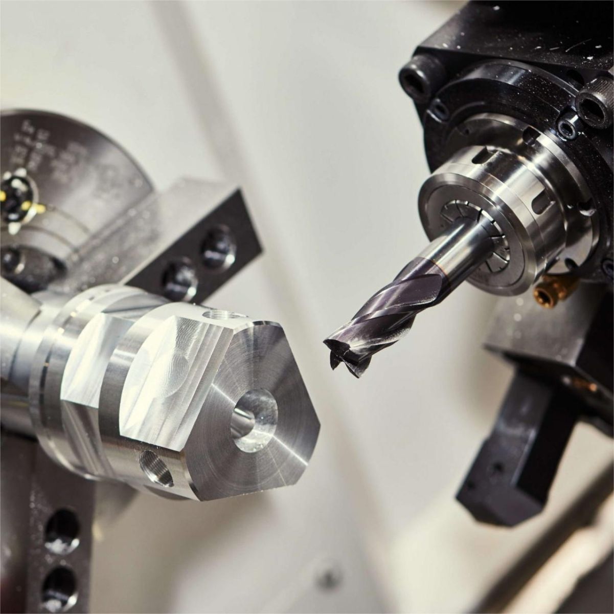
(1) rough machining. For three-dimensional machining of pentahedra, rough machining is relatively difficult to handle. First, use the vertical milling head to machine the upper end, and then replace the horizontal milling head to machine both sides of the X axis and the Y axis. Due to the fact that the five faces are processed separately, full consideration should be given to the connection and transition between each region during programming. It is not allowed to make the boundary of the repeated processing area too large, nor to prevent the boundary of each region from not being connected, resulting in unprocessed blind spots and causing trouble for subsequent processing. In addition, when the equipment is used for vertical milling, the spindle can withstand a greater force than when it is used for horizontal milling. Therefore, when the tool overhang is allowed, the machining area of the vertical milling can be increased to reduce the rough machining range of the horizontal milling. At the same time, attention should be paid to the spindle speed and cutting feed of the horizontal milling, which should be lower than the corresponding milling parameters of the vertical milling. Select diameter Φ A 32 mm flat bottom rounded milling cutter with a blade rounded to R5 mm, commonly known as a cow nose cutter.
(2) Semi precision machining. Select diameter Φ 25 mm or diameter Φ 20 mm ball head cutter for semi precision machining, with vertical to horizontal conversion zone processing. Considering the fast precision machining speed of the next process, programming should also pay attention to the handling of the boundaries of each processing area.
(3) Fine machining. Select diameter here Φ 16 mm or diameter Φ 10 mm ball head cutter for precision machining, vertical to horizontal conversion zone processing, pay attention to the treatment of tool marks. The efficiency of precision machining depends on the performance of the machine tool. If the equipment has the ability to process at high speeds (with spindle speeds of over 8000 r/min at the boundary of the area), it can greatly improve the machining efficiency, enhance the surface smoothness of the parts, and reduce the polishing workload of subsequent bench workers.
(4) Root cleaning processing. Due to the small fillet at the local reinforcement of this piece, which is R 3mm, it is necessary to process the fillet separately. Utilize diameter Φ Processing with a 6mm ball head cutter, with two vertical and horizontal directional changes. from Φ 10mm tool transitions directly to Φ 6 mm, with a relatively large margin at the rounded corner, suitable step spacing and feed rate should be used for machining to prevent damage to the tool. Depending on the size of the cutting tool in the previous process, it can be used Φ Before processing 6mm, add a processing step to reduce the margin at the rounded corner.
3 The application difficulties and treatment of UG software in pentahedral machining center programming
In the three-dimensional processing of general CNC systems, including vertical and horizontal machining centers, the tool spindle direction is always consistent with the graphical ZM direction ( as shown in Figure 4 ). However, the OKUMA CNC system of the gantry pentahedron machining center, in the process of vertical and horizontal conversion of three-dimensional machining, the machining coordinate system always remains unchanged, that is, the ZM direction remains unchanged, and the programming processing must be realized by controlling the change of the axial direction of the tool. The following discusses how to control the axial change of the tool, as well as the modification of the relevant programming parameters and post-processing files after the axial change.
( 1 ) In the process of vertical-horizontal conversion, the machining coordinate system remains unchanged. When lateral machining is needed, CAM programming is mainly realized by controlling the axial direction of the tool. In UG software, the default tool axis is the ZM direction, which can specify the vector direction for the tool axis ( as shown in Fig.5 ). The tool axis is negative along the YM and adjusted according to the specific workpiece. The adjustment of the tool axis is specified under the tool axis option of the UG programming operation control panel. There are many ways to control the tool axis. It should be noted that after the tool axis is specified, the tool axis direction shown in the software should point to the tool. In Figure 5, the tool axis direction is negative along YM, not positive along YM, which is easy to make mistakes.
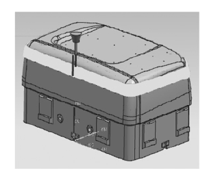
Fig. 4 Vertical three-dimensional machining tool path
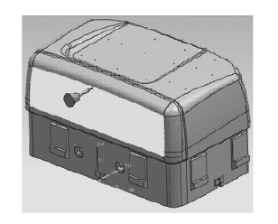
Fig. 5Horizontal 3D machining tool path
(2) When the tool axis is specified according to the vector, the setting of the feed and retreat points and the safety plane is more complex than the corresponding end milling setting. The safety plane should be set perpendicular to the tool axis and away from the workpiece. During the programming process, attention should be paid to the safety of the cutting tool and reasonable avoidance during cutting to prevent unsafe factors during the machining process. In versions after UGNX4, setting these parameters is relatively easier. (3) To customize the post processing file for the CNC system again, the NC code generated using the software's built-in post processing file is not suitable for pentahedral machining and can be modified in the software's built-in post processing file. Use the UG post processing constructor in combination with TCL language (open TCL format file using JediEdit software) to modify the axial transformation part code:
BLOCK_TEMPLATE rapid_spindle_z {
G_adjust[$mom_adjust_code]
G_motion[$mom_sys_rapid_code] G_mode[$mom_sys_output_code($mom_output_mode)]
#Z[$mom_pos(2)]
Z2[$mom_z]
H[$mom_tool_adjust_register]\opt M_coolant[$mom_sys_coolant_code($mom_coolant_status)] \opt }
- The beginning of the NC code generated after post processing during the pentahedral end milling shown in Figure 4 in the text is:
N1G15H01
N3G17G0G90X26.002Y-12.729S2500M03
N5G56Z750.000H02
The beginning of the NC code generated after post processing during the pentahedral horizontal milling shown in Figure 5 in the text is:
N1G15H01
N3G18G0G90X-17.704Y-38.700S2500M03
N5G55Z636.322H02
The main difference between the two NC codes mentioned above is the changes in the G code, which are G17, G56, G18, and G55. These reflect the different machining planes and tool axial orientations. By customizing the UG post-processing file, reasonable NC codes can be generated. The above code is for the OKUMA CNC system. Different CNC systems use different post-processing files, and the content involved here is extensive and will not be repeated.
In short, using appropriate programming methods and post processing techniques can solve related problems and make large pentahedra play an important role in CNC machining.
FAQs for Gantry Pentahedron Numerical Control Center:
1. What sets apart the Gantry Pentahedron CNC Center from conventional machining systems? In this section, we will explain the fundamental differences between traditional machining centers and the advanced Gantry Pentahedron CNC Center. Unveil how the additional two rotary axes (A and C) empower this machining marvel to handle complex, multi-sided tasks with unparalleled precision and efficiency.
2. How does the Gantry Pentahedron CNC Center optimize large parts machining? Here, we will outline the various ways the Gantry Pentahedron CNC Center revolutionizes the manufacturing of large parts. From enhanced productivity and versatility to reduced setups, readers will grasp the significant advantages of utilizing this state-of-the-art system for their machining needs.
3. Which industries can benefit from the Gantry Pentahedron CNC Center? This section will highlight the diverse industries that can leverage the capabilities of YICHOU's Gantry Pentahedron CNC Center. From aerospace and automotive to energy and defense, discover how this technology is reshaping precision machining across various sectors.
4. Why choose YICHOU for Gantry Pentahedron CNC machining services? In this segment, we will showcase YICHOU's expertise and dedication to providing exceptional Gantry Pentahedron CNC machining services. Readers will learn about our commitment to customization, shorter lead times, cost-effectiveness, and global reach, making us the ideal partner for their international large parts manufacturing projects.
5. What unique solutions can YICHOU offer with the Gantry Pentahedron CNC Center? Here, we will delve into the specific benefits of choosing YICHOU as a manufacturing partner. From tailored solutions to intricate designs, faster turnarounds, and seamless logistics, readers will discover the competitive edge YICHOU's Gantry Pentahedron CNC Center can bring to their projects.
4:Conclusion
In this concluding section, we will summarize the key takeaways from the blog and reinforce YICHOU's position as a leading provider of Gantry Pentahedron CNC machining services worldwide. Encourage readers to reach out to us for their large parts manufacturing needs, and let them know that YICHOU is committed to exceeding expectations and delivering unmatched precision and quality.
Get Quote
- Visit our website: https://www.nbyichou.com/
- Email us: [email protected]
- Call us/whatsapp: +86 13355741031
- Chat with us: Live chat support available on our website