Abstract:With the rapid development of infrastructure construction,engineering construction related to mechanical and electrical engineering has been rapidly developed,especially the surveying and mapping of mechanical parts and CAD drawings have received much attention.Therefore,this article mainly analyzes the connotation and function of the surveying and mapping of mechanical parts and CAD drawing,and proposes the application strategy of the surveying and mapping of mechanical parts and CAD drawing.
Key words:mechanical parts;surveying and mapping;CAD drawing;application;research
1 Introduction
.jpg)
Surveying and mapping of mechanical parts and CAD drawing is a very practical and professional course. It usually has strong requirements for people 's analytical ability and spatial imagination. Only in this way can students have corresponding drawing practice, which is difficult for most students to learn and apply. When studying and applying the knowledge of surveying and mapping and CAD drawing of mechanical parts, we usually study, consolidate and improve the relevant knowledge points and drawing theory of surveying and mapping and CAD drawing of mechanical parts according to relevant tasks. Through the effective combination of theory and practice, it can not only effectively avoid the single push of knowledge points, mechanized memory drawing standards, and boring learning drawing theory, but also make drawing more standard and standardized, so that students ' interest in learning and self-study consciousness of mechanical parts mapping and CAD drawing can be effectively improved. At the same time, it promotes students to deeply understand the application significance of the course content in real life, and promotes the expansion of teaching connotation, so that the teaching quality and effect of mechanical parts mapping and CAD drawing can be significantly improved.
2 Summarization of mechanical parts mapping and CAD drawing
2.1 Mapping of mechanical parts
2.1.1 Mapping of mechanical parts
The surveying and mapping of mechanical parts is a new course with the characteristics of vocational education, which is mainly based on the development concept of systematic course of working process. It is mainly based on the premise of deep cooperation with enterprises, and enterprises to develop a course of work-integrated learning. The main purpose of this course is to cultivate students ' own professional awareness, ability and post skills.
2.1.2 The mapping steps of parts
Firstly, component analysis. In the initial design, the components were mainly assigned corresponding roles and functions on the machine. In order to achieve a complete and accurate expression of the surveying and mapping process of components, many surveying and mapping components are carefully analyzed, and the dimensions and accuracy of the components are clearly marked. The types of components are fully understood, and through the role of the machine, the materials used and related processing methods are understood. The materials, types, functions, and rough machining methods used in the machine are also understood.
Secondly, the expression scheme of parts view is defined. In order to fully meet the production needs, the series profile of parts needs to be displayed in different ways according to its structural form and functional form. The types of parts and components clearly point out that the scheme is usually manifested in two aspects : first, the selection of the main view. The selection of the main view should follow the following principles : 1 the characteristics of the shape of the parts ; the main view reflects the parts processing and its working position as much as possible. If it is impossible to accurately determine the relevant position, it is necessary to select some natural positions. Second, select some different views and demonstration schemes. If the main view cannot fully present the internal structure and the shape of the parts, it is necessary to select some different views or display schemes. It can be seen that the overall concept of detail needs to pay attention to each view or scheme, and the details are not the only choice.
Again, through the visual freehand sketches of parts. In this step, it is usually divided into five steps :
1 Define the position and proportion of the drawing, roughly define the area occupied by each view, and build the center line and baseline through the main view.
2 The internal structure and shape of the parts are elaborated in detail, and the relevant drawings are found and deepened, paying attention to the proportion between the parts structure.
3 Surveying and mapping all the size lines to be marked, and marking according to each size, pay attention to repeat or incorrect size.
4 Filling technology requirements : parts of the surface of the specific roughness measurement, dimensional tolerances, parts measurement, heat treatment, mold tolerances and other related requirements.
5 Check and modify the map, fill in the title, the implementation of sketches.
.jpg)
Finally, the working diagram of mechanical parts is drawn. Because in the mapping of sketch details, subject to certain restrictions, many problems usually can not be solved in the measurement process. Generally speaking, the organization and modification of the details of the sketch, through the formal parts drawings for production, after the approval of production. The calibration of the sketch, in the design of standard parts, need to pay attention to look at the table, want to show the correct size and mapping parts of the working drawings, in the parts of the drawing mapping, all parts of the mapping work is completed.
2.1.3 Specific methods and steps of parts surveying and mapping
Firstly, the structure of the parts is understood and analyzed. When surveying and mapping mechanical parts, it is necessary to pay attention to the analysis and research of mechanical parts, understand the working principle, assembly relationship and structural characteristics of surveying and mapping.Secondly, draw the corresponding equipment schematic diagram, which mainly represents the assembly relationship and mutual position of the components. It is an important basis for reassembling and drawing assembly drawings after component disassembly. Once again, disassemble the mechanical components. When disassembling, attention should be paid to the principle of "restoring the original machine". Purchased components or non detachable parts should be kept as close as possible, and destructive disassembly methods should be avoided. Before disassembling, important dimensions should be measured, such as assembly gaps and extreme positions of moving parts. Finally, draw a sketch of the mechanical components. Sketches of components are usually hand drawn at the surveying site, without maintaining strict proportions with the tested components, but must include all the content of the component diagram. Afterwards, draw the corresponding assembly diagram based on the assembly schematic and component sketches.
2.2 CAD drawing
1 Start-up and exit of CAD ; cAD user interface and working interface ; set up a habitual drawing environment ; cAD drawing method ; recognizing the environment of CAD drawing ; the management of graphic files.
2 The drawing method of relatively simple graphics such as points and lines ; familiar with auxiliary mapping skills ; flexible and accurate implementation of CAD drawing commands, and through the state bar aided drawing method ; the proportion of drawing preparation and style design.
3 Through the editing command and the editing function of the pinch point of the system, the complex graphics are mapped, which is the filling group of the graphics, and the mapping method of the complex graphics is fully grasped.
4 Using the control function of graphics and layer features ; promote the improvement of mapping efficiency through block mapping ; fully grasp the application methods of blocks and layers, and promote the improvement of drawing efficiency.
- Mark the corresponding size and text to the graphics, fully grasp the size and text labeling method.
- 6 Three-dimensional graphics rendering, according to the three-dimensional graphics environment settings, fully grasp the relatively simple three-dimensional graphics rendering method.
- 7 Graphic printing, fully grasp the method of printing and output graphics.
3 The mapping and CAD drawing of mechanical parts
The technical application of mechanical parts mapping and CAD drawing, mechanical parts mapping and CAD drawing is usually the mapping of parts, CAD drawing, manual drawing, three-dimensional modeling, quality control, assembly knowledge and skills, professional quality, teamwork and other abilities to implement comprehensive training, the specific performance is as follows :
First, it helps to standardize the drawing standards. Mechanical engineering drawings are known as the ' common language ' in the engineering field. Drawing annotation usually refers to the actual ' grammar ' of the ' common language '. Therefore, drawing standards usually have an important influence in the engineering field. At present, the relevant standard theory of mechanical parts mapping and CAD drawing is an important way for mechanical parts processors to learn standards, but the specific application of national standards is not ideal, which will affect their reading and drawing, resulting in a disconnection between theory and practice. Relevant personnel through the mapping of mechanical parts and CAD mapping related technical knowledge and content extraction, such as gear shaft mapping, need to clear the gear tooth number and modulus calculation, determine the gear accuracy level ; when measuring, it is necessary to pay attention to the standardized and rational use of measuring tools and correct reading ; when drawing, you need to be able to quickly and standardized freehand drawing on the coordinate paper, so as to lay a good foundation for CAD drawing, and complete the three-dimensional map and plane map through CAD drawing, usually including the map, frame, line type, proportion, view selection, tolerance, annotation, technology and other related requirements. In the specific surveying and mapping, it is mainly to study and apply the standard of drawing, so as to ensure the visualization, process and concretization of the mapping of mechanical parts and the drawing of CAD drawing.
Secondly, it helps to make mechanical component surveying and CAD drawing more interesting. In the process of surveying and mapping mechanical components and CAD drawing, using the same drawings cannot effectively integrate relevant information through learned knowledge, and the understanding of drawings is also relatively shallow. Therefore, taking the surveying and mapping of simple mechanical components as an example, guide students to enter the door of spatial analysis. Taking a cylinder as an example, a three-dimensional drawing can be first surveyed and generated into a two-dimensional plan view, which can be selected in different main view directions to form different views, fully reflecting the fun of mechanical component surveying and CAD drawing.
Finally, it is helpful to the effective combination of theory and practice. In the mapping and CAD mapping of mechanical parts, the mapping and CAD mapping knowledge and technology of abstract mechanical parts can be effectively combined with practical work practice, such as the mapping and CAD mapping of gear pumps. The parts of the gear pump can be analyzed first, and the gear pump can be divided into active gear shaft, driven gear pump, pump cover, pump body, spring, bolt, oil plug, gasket and other parts, and these mechanical parts are used as carriers for mapping and mapping. The application of surveying and mapping of mechanical parts and CAD drawing can transform discrete and abstract knowledge points into specific mechanical engineering applications, and combine the surveying and mapping of mechanical parts with the content and professional standards of CAD drawing, so as to realize the effective application of surveying and mapping of mechanical parts and CAD drawing.
.jpg) 4 The practical application of mechanical parts mapping and CAD drawing
4 The practical application of mechanical parts mapping and CAD drawing
4.1 The practical application of mechanical parts mapping and CAD drawing
4.1.1 Grasp the damage status of mechanical parts accurate information
Engineers need to fully understand how many pieces of mechanical parts are damaged, whether the damage of mechanical parts can be repaired, and whether there can be spare parts. If all the above conditions are denied, it is necessary to make clear whether the drawings of damaged mechanical parts are exquisite. In a certain situation, the drawings can be handed over to the processing department for production. If not, some damaged parts should be investigated and found out.
4.1.2 The method of entity mapping
The mapping process of mechanical parts starts with measuring the size of the connecting parts of the parts, so as to promote the construction of exquisite tolerances during assembly, and to correct them according to specific measurements and related tolerance standards. The actual measured values and correction values need to be marked in the sketch, as shown in Figure 1.
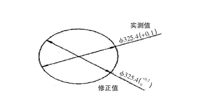
Fig.1 Solid measurement sketch
In terms of assembly dimensions, if the conditions, that is, the environment and time allow, at least 3 times of measurement and data reading are required to verify the dimensional accuracy. After the accurate investigation and mapping of the key dimensions, the size of the parts that do not match is measured, that is, the size and shape. Generally speaking, the designed size value needs to meet the load and structural requirements of the component mounting, and there is no strict requirement for the accuracy of the parts. For example, the actual thickness of the coupling journal, gear web, etc., is shown by the dimensions A, B1, and B2 in Figure 2. The size does not need to be measured many times, as long as the base value is measured.
4.1.3 Sketch drawing
After the completion of surveying and mapping, it is necessary to carry out surveying and mapping according to the drafting of mechanical parts. Sketch is usually the premise and foundation of formal parts processing, which needs to accurately reflect the structure, shape and size of the workpiece to be mapped.In addition to clearly marking the dimensions of the sketch, it is also necessary to clearly mark various tolerances, namely positional tolerance, shape tolerance, surface roughness, and fit. Usually, it is necessary to mark the dimensions of mechanical components that match the test piece. When conducting on-site surveys and surveying, it is necessary to clarify the technical requirements and material surveying of the components, which can be used as a reference for the preparation of formal mechanical component processing drawings. The accuracy of sketches usually has a decisive impact on the quality of drafting, which is also a major component of drafting work. And use relevant knowledge as the basis for sketching, presenting the accurate shape of the components, the position of each machined mechanical component, and the precise size of the fit.
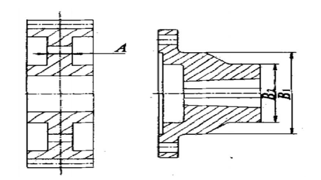
Fig.2 Size mapping of non-matching parts
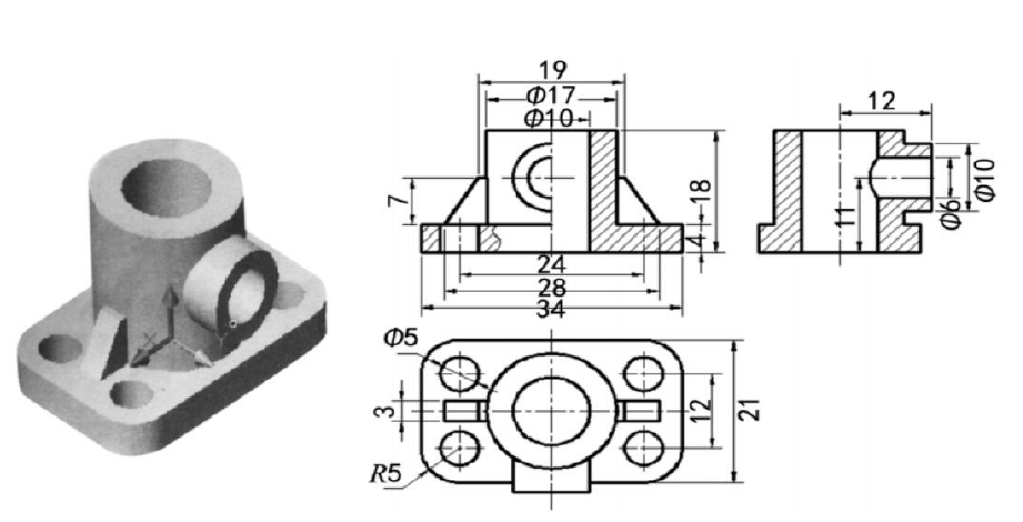
Fig.3 3D rendering and three views of bearing seat drawn by CAD
4.1.4 According to the technical selection of parts used in the material and heat treatment requirements
In the selection of mechanical parts, it is necessary to pay attention to the operation requirements, economic requirements, process requirements, reasonable material selection, normalization and annealing according to the performance of the machine, and select the correct tempering, quenching, surface heat treatment, etc., which have a positive impact on the performance and promote the use of parts. Life and processing quality improvement. In the selection of materials, it is necessary to fully consider the force direction, load properties, working temperature and other related factors, as well as friction properties, environment and so on. Considering the constant stress components, some materials that do not deform can be selected, impact materials can be tolerated, and materials with large viscosity differences can be selected. For refractory materials, it is more suitable for parts. The parts that work through corrosion and high temperature environments need to be corrosion-resistant materials. If the parts rub and slide, they need to be wear-resistant materials. When selecting materials according to process requirements, it is necessary to fully consider the difficulty of assembly and other related factors, as well as the size and processability of mass production. If the mechanical parts are complex in shape or mass production, it is necessary to use casting materials, as far as possible to use easy-to-cut materials. Typical technical requirements usually include the relevant requirements for the mechanical properties and chemical composition of the material, the heat treatment requirements and processing requirements of the material, the rounded corners and inclined plane instructions without fillers, and the balance test requirements of the parts.
4.1.5 Formal processing drawings mapping and archiving
The formal processing drawings are mainly based on sketches and standard assembly processes. When surveying and mapping formal mechanical parts, it is necessary to clarify the drawings, parts shapes, and reflective designs that must be used, such as local reinforcement and cross-section of mechanical parts. At the same time, it is also necessary to pay attention to the reference manual of the sketch and the inspection of the sketch size. The data used should meet the relevant requirements of standardization and standardization, and be consistent with the basic size of the mechanical parts, and the accuracy level of the parts should be correctly selected. Technical requirements and heat treatment methods need to be correctly marked on the drawings of mechanical parts, so as to lay a solid foundation for later technical transformation and maintenance.
.jpg) 4.2 The application of CAD drawing
4.2 The application of CAD drawing
In the process of mechanical drawing, it is usually three-dimensional to two-dimensional. Taking the drawing of bearing seat as an example, the map maker usually models the three-dimensional drawing through CAD drawing according to the design requirements, so as to present the effect diagram of Figure 3. In order to facilitate processing, it is necessary to gradually convert the three-dimensional model into a two-dimensional view through the correlation relationship. The conversion process is as follows : open the space of the model, move the lower left corner to the origin of the coordinates ( 0,0,0 ), convert to the layout, and double-click the inside of the viewport to call out the entity toolbar and the view toolbar.
Turn the viewport into a top view, tap the contour smelting command, and then select the entity. After confirmation, return three times to form the corresponding main view. The left view and the top view of the mechanical parts are mapped by the same method. At this time, the formed three views are not in the same plane. After the alignment and smelting command, the three views of the bearing seat can be effectively converted. Through the generated two-dimensional map, the section view is drawn, and the necessary size and text are marked, and the drawing of the graph is finally completed. In the whole process of CAD drawing, it is necessary to correctly operate the bearing seat modeling, fully grasp the skills and methods of converting three-dimensional into two-dimensional in CAD drawing, so as to realize the rapid drawing of bearing seat parts pictures, which not only saves the drawing time, but also significantly improves the drawing accuracy. At the same time, the clear drawing and structure of the graphics are clear, which is not only convenient for the processing of the later parts, but also enables the processing technology of the parts to use the structure of the three-dimensional model to operate correctly, so as to realize the successful completion of CAD drawing.

To sum up, the mapping of mechanical parts needs to accumulate rich experience through the participation of equipment maintenance and the structural observation of mechanical parts. With reference to relevant books, the cost, life, cost performance and other related factors of mechanical parts should be fully considered in order to facilitate the effective mapping of mechanical parts. At the same time, the application of CAD drawing can also give full play to the function and role of the software. Accurate and efficient mapping should be consistent with the drawings of mechanical parts required by national standards, so as to promote the effective application of mechanical parts.
FAQ
-
What Are the Key Principles of Mechanical Parts Drawing in CAD? Explore the essential guidelines for creating accurate and detailed mechanical parts drawings using CAD software. Learn about dimensions, annotations, tolerances, and best practices for ensuring manufacturing precision.
-
How to Create Professional CAD Drawings for Mechanical Assemblies? Discover step-by-step instructions on producing polished and comprehensive CAD drawings for complex mechanical assemblies. Learn techniques for organizing components, creating exploded views, and presenting detailed part information.
-
What Is the Importance of 3D Modeling in Mechanical Design and CAD? Understand the significance of 3D modeling in modern mechanical design and CAD. Learn about the advantages of visualizing components in three dimensions, optimizing designs, and fostering effective collaboration among teams.
Get Quote
- Visit our website: https://www.nbyichou.com/
- Email us: [email protected]
- Call us/whatsapp: +86 13355741031
- Chat with us: Live chat support available on our website