Abstract:Based on the comparison of CNC lathe processing technology and traditional processing technology, the key problems in CNC lathe processing technology are analyzed, and the design method of CNC lathe process is introduced. Through the example programming analysis, it shows that the correct analysis and design of CNC lathe processing technology is helpful to improve the processing quality and production efficiency of parts, and provide experience and reference for actual production.
Keywords :CNC lathe ; process design ; process analysis ; CNC programming
1 Introduction
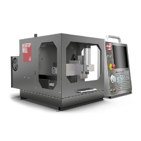
CNC machine tool is a kind of electromechanical integration processing equipment with high technology intensity and high degree of automation. It is the product of high and new technology such as computer, automatic control, automatic detection and precision machinery. CNC lathe is one of the most widely used CNC machine tools. Numerical control machining has changed the traditional machining process. In numerical control machining, datum selection and positioning error must be considered. The problem that the positioning datum does not coincide with the design datum still exists, but the measurement datum and the process datum can be consistent with the design datum, so as to avoid the dimension chain solution and the error caused by it. The coordinate method with control precision is used to determine the shape and size of each section in NC machining programming. At the same time, the positioning accuracy of the servo system is also very high ( more than 0.001 mm ), which can easily ensure the dimensional tolerance and shape tolerance of the product. Therefore, even if the datum is not coincident or the datum is not uniform, the influence on the accuracy of the workpiece can be controlled very little. The positioning error is composed of two parts : the reference non-coincidence error and the reference error. Benchmark error in the traditional processing of the use of fixtures for mass production, the impact on the processing of parts is very prominent, but the frequent use of fixtures in CNC machining has been rare, parts in the processing before the knife, often for the actual surface of the workpiece directly on the knife, the process is rarely re-clamped or transposition, the impact of fixtures has been greatly reduced, so compared with the traditional processing technology, CNC machining positioning error is no longer the main factor, which is one of the advantages of CNC machining process.
2 CNC lathe processing technology analysis
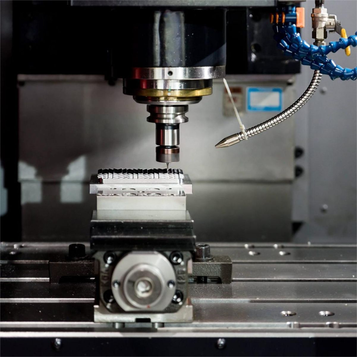
The analysis of CNC lathe processing technology involves a wide range of aspects. From the two aspects of possibility and convenience, on the one hand, the size data in the part drawing should meet the programming convenience. On the drawings of CNC machining parts, it is best to mark the size with the same benchmark or directly give the coordinate size. In manual programming, to calculate the coordinates of each node ; in automatic programming, all geometric elements that constitute the contour of the part are defined. On the other hand, the structural manufacturability of each processing part of the part should conform to the characteristics of CNC machining. On the premise of meeting the requirements of use, it is best to adopt a unified geometric type and size, so as to reduce tool specifications and tool change times, and simplify programming. Numerical control machining should try to use a unified reference positioning, otherwise it will cause the shape and position error of the workpiece processing due to the multiple installation and positioning errors of the workpiece. Analyze the machining accuracy required by the parts, including whether the dimensional tolerances, geometric tolerances, surface roughness, etc. can be guaranteed, whether there are redundant dimensions that cause contradictions or closed dimensions that affect the process arrangement, etc.
3 CNC lathe machining process design
3.1 Design of process route
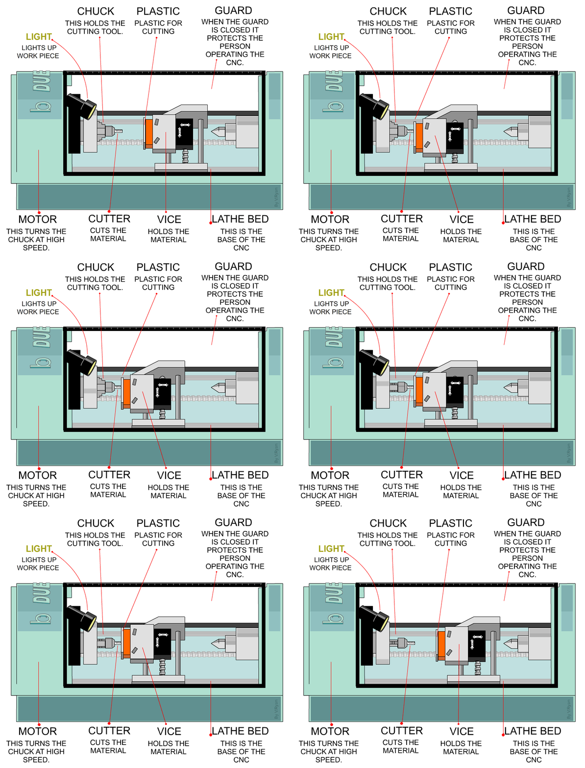
The machining process of CNC lathe is divided into several stages. Rough machining stage : mainly to remove most of the machining allowance, so that the blank is close to the finished product in shape and size. Semi-finishing stage : to make the main surface to achieve a certain precision, to prepare for the finishing of the main surface, and to complete the processing of some secondary surfaces. Finishing stage : the main surface to meet the quality requirements of the drawings. Finishing stage : For the surface with high quality requirements, it is necessary to carry out finishing processing, which is mainly used to further improve the dimensional accuracy and reduce the surface roughness value.
.jpeg)
3.2 Fixture and tool design
Combination fixture, general fixture or adjustable fixture should be preferred in single small batch production. In batch production, special fixtures can be used. It is also required that the fixture is installed accurately on the CNC machine tool and can coordinate the size relationship between the workpiece and the machine tool coordinate system. Generally, standard cutting tools are preferred, and various composite cutting tools and other special cutting tools can also be used. A variety of advanced tools can also be selected, such as indexable tools, cemented carbide tools, ceramic coated tools and so on. The type, specification and precision grade of the cutting tool should meet the processing requirements, and the cutting tool material should be compatible with the part material.
3.3 Design of tool path
Determine the tool path should consider to ensure the processing quality, as far as possible to shorten the tool path, programming calculation to be simple, the number of program segments to be less, and ' less tool change ', ' less empty tool ' and so on.
3.4 Design of cutting parameters
The cutting parameters mainly include cutting depth, spindle speed and feed rate. The cutting speed has the greatest influence on the tool durability, followed by the feed rate, and the cutting depth has the least influence. Considering the relationship between cutting parameters and tool durability, when selecting the cutting parameters for rough machining, a large cutting depth should be preferred, followed by a large feed rate, and finally a reasonable cutting speed. Tool tip wear is often an important factor affecting machining accuracy during finishing. Therefore, tool materials with good wear resistance should be selected and made to work within the optimal cutting speed range as much as possible.
4 Typical parts CNC lathe machining process analysis and programming examples
Using GSK980T CNC lathe, the 45 # steel bar blank with a diameter of φ26mm is processed into the parts shown in Fig.1.
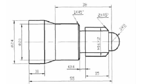
Fig.1 Parts drawing
4.1 Processing route
Following the principle of first main and second, first coarse and then fine processing, the fixed cycle instruction is used to roughen the outer contour, and then finish the processing, and then the tool groove is returned, and then the thread is processed and finally cut off.
4.2 Clamping method and selection of tool setting point
The three-claw self-centering chuck is used for self-centering clamping, and the tool setting point is selected at the intersection of the right end face of the workpiece and the rotation axis.
4.3 Select the tool
According to the processing requirements, four knives are selected, No.1 is a rough machining cylindrical turning tool, No.2 is a finishing cylindrical turning tool, No.3 is a turning thread tool, and No.4 is a grooving tool. The trial cutting method is used to align the tool, and the end face is processed at the same time.
4.4 Determination of cutting parameters
The spindle speed of rough turning is 500r / min, and the feed speed is 150mm / min. The spindle speed of finish turning is 800r / min, and the feed speed is 100mm / min. When grooving and turning thread, the spindle speed is 300r / min, and the feed speed is 30mm / min.
4.5 Programming
The intersection point of the axis line and the center of the ball head is determined as the programming origin.
5 Process analysis
5.1 Knife
Before machining, the parts should be operated on the tool, that is, the tool should be adjusted to the starting point of the program. There are many ways to align the tool. The following is the commonly used trial cutting method :
( 1 ) Before the tool is aligned, the base tool is required to be adjusted back. Method : If your base tool is a tool at position 1, enter T0100 → key → cycle start.
( 2 ) Make the knife in the memory clear 0. Method : Enter the ' knife ' page, move the cursor to the corresponding position and input X0 → key, Z0 → key, and so on.
( 3 ) Using ' hand wheel or manual mode ' to cut the end face A side of the workpiece, as shown in Figure 2, after cutting, the tool holder is not moved, the Z direction relative coordinate W is cleared ( first let the W cursor flash, and then press the key ), mode, MDI page, input G50 Z0 ; → Press the key, so far, establish the working coordinate system in the Z direction of the reference tool tip ( the machine tool clarifies the processing origin in the Z direction of the reference tool tip ) ; remove tool holder. Cut a small section of the outer circle B surface, as shown in Fig.3. The X direction of the tool holder remains unchanged, and the tool holder is moved out along the + Z direction. The relative coordinate U in the X direction of the main shaft is zeroed ( the U cursor is flashed first, and then the key can be pressed ) to measure the diameter of the cut outer circle section 24, mode, MDI page, input G50 X24 ; → Press the key, so far, establish the working coordinate system of the reference tool in the X direction, ( the machine tool defines the machining origin of the reference tool in the X direction ), and return the reference tool to the complete position.
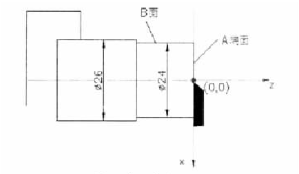
Fig.2 Tool setting process 1
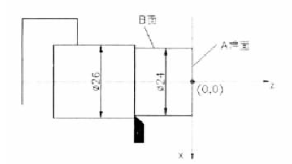
Fig.3Tool setting process 2
(4)Call up tool 2 (T0200) without tool compensation,<manual>/<handwheel>mode,<position>page (relative coordinates), and move the tool holder close to the workpiece. The spindle rotates forward, and the tool holder does not move after the No. 2 tool tip lightly touches the end face →<Tool Compensation>page. Move the cursor to the corresponding tool deviation position, press the X key →<IN>key; Move the tool holder so that the tip of Tool No. 2 lightly touches the cut outer circle and the tool holder does not move. On the<Tool Compensation>page, move the cursor to the corresponding tool deviation position and press the Z key →<IN>key.
(5)The steps for aligning knives 3 and 4 are the same as those for knife 2.
.jpg)
5.2 Accuracy control in machining process
There are two methods of machining accuracy control in actual production, namely, modifying the program and modifying the tool compensation.
( 1 ) Modify the program. This method is mainly used to control the size of the thread part in the program. For example : to turn M16 × 2 thread, the program is : G76 P040260Q60 R0.02 ; g76 X13.4 Z-20 P1300 Q600 F2 ; if the thread processed according to the program is not screwed in, we will modify the small diameter of the thread. If a tooth can not be screwed in, it can be modified from X13.4 to X13.3.If only two or three teeth are screwed in, it can be modified from X13.4 to X13.35.When modifying, remember not to modify too much at one time. At the same time, in order to save time, change Q600 to Q1000, and then use the jump method to process the new thread until it is qualified.
( 2 ) Modify tool compensation. The cutting part of each tool is different, and in the cutting process, the dimensional accuracy of the parts will be unqualified due to the reasons of tool setting, measurement, tool wear and so on. In view of this situation, we can use the tool compensation of each tool to realize the control of the accuracy of the parts. For example, for the thread of M16 × 2, the theoretical value is 16.5 and the actual result is 16.32 when the outer circle of this section is roughed, which indicates that the parts after rough turning are smaller. In order to ensure the final accuracy of 16, it is necessary to modify the way of tool compensation before finishing. Assuming that the X of the original tool compensation of the tool for processing the program is 12.66, then we will change the tool compensation to X12.66 ( 16.5-16.32 ) = 12.84.
6 Conclusion
The process design in CNC machining is an important part of CNC programming. Whether the process design is reasonable or not will be directly related to the efficiency of CNC lathe, the processing quality of parts, the number of tools and the economy. Therefore, when formulating the NC machining process of parts, full and comprehensive process analysis should be carried out, and the process should be designed flexibly and reasonably. Practice has proved that the selection of reasonable and efficient process methods and processing routes is of great significance to the preparation of high-quality numerical control programs and the improvement of processing quality, production efficiency and economic benefits.
Get Quote
- Visit our website: https://www.nbyichou.com/
- Email us: [email protected]
- Call us/whatsapp: +86 13355741031
- Chat with us: Live chat support available on our website