Subtitle: Why leading utilities, renewable energy developers, and industrial plants are switching to next‑generation step‑down and isolation transformers for unmatched reliability.
---
Introduction: The Hidden Cost of Inaccurate Voltage Measurement
In any power system, from a 400 kV transmission corridor to a 33 kV wind farm collector, voltage measurement errors cost money. A 0.5 percent metering inaccuracy on a 100 MW solar plant can translate into tens of thousands of dollars in unbilled revenue each year. Worse, a voltage transformer that fails due to ferroresonance or partial discharge can trigger substation blackouts, equipment damage, and serious safety hazards.
Voltage transformers (VT) and potential transformers (PT) are not merely auxiliary devices. They are the foundation of reliable protection, precise billing, and stable control. When correctly selected and installed, a high‑voltage transformer provides both accurate step‑down scaling and galvanic isolation. This dual function protects sensitive relays, meters, and human lives.
This guide delivers actionable insights for procurement managers, system integrators, and utility engineers. You will learn how to differentiate between VT and PT, select the right step‑down voltage transformer for each voltage level, and avoid the most common failure modes. Most importantly, you will discover how partnering with a certified global supplier reduces total cost of ownership and eliminates project delays.
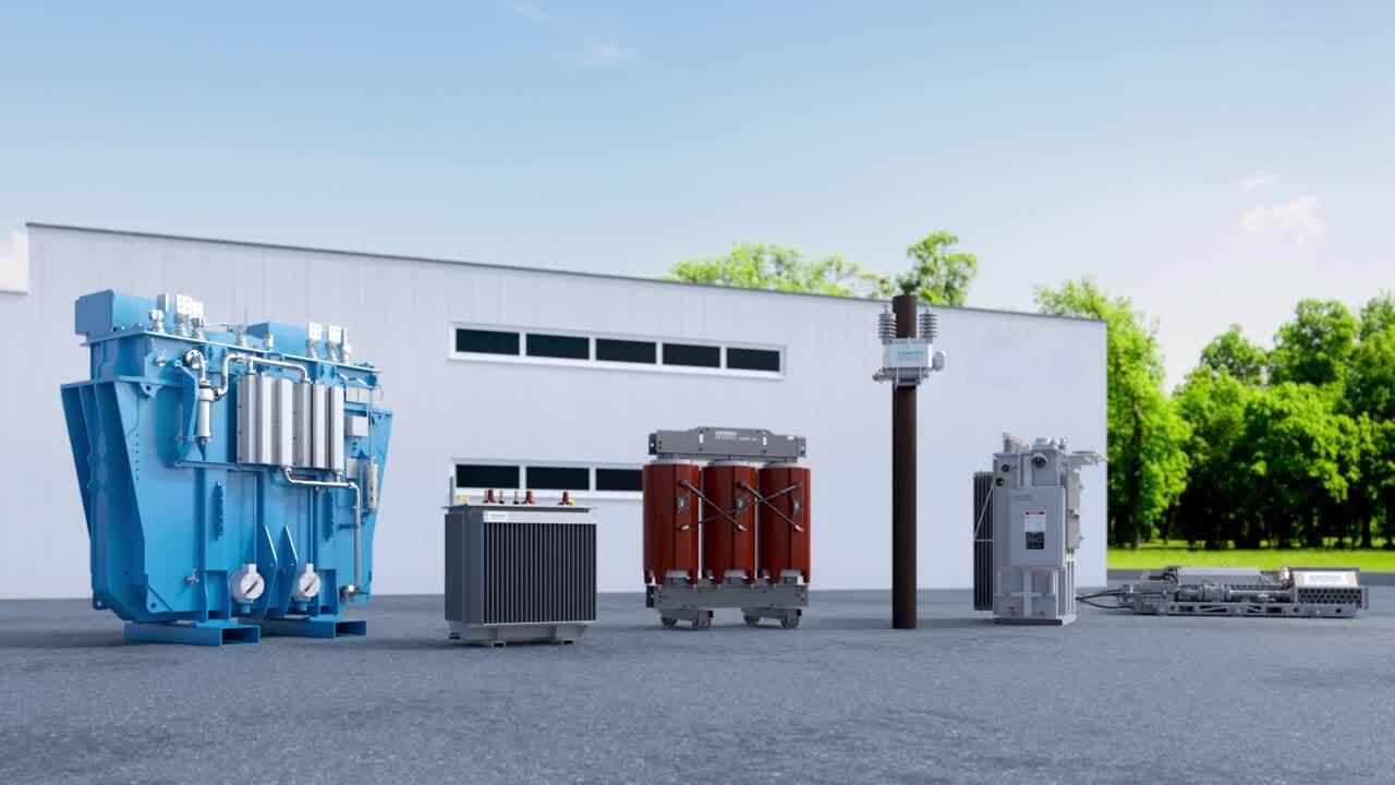
Chapter 1: VT vs. PT – No More Confusion
Industry professionals often use voltage transformer and potential transformer interchangeably. In practice, both refer to instrument transformers that reproduce a primary voltage as a proportional secondary voltage. The difference is primarily regional. IEC standards prefer VT, while ANSI / IEEE documents commonly use PT.
What truly matters are performance parameters, not names. A quality VT or PT must deliver:
· Ratio accuracy: class 0.1 to 1.0 for metering, class 3P or 6P for protection.
· Low phase displacement: typically within minutes of arc.
· Sufficient burden capacity: from 25 VA to 500 VA depending on application.
· Robust insulation: oil‑paper, cast resin, or SF6 gas.
For international projects, the most critical decision is conformity to IEC 61869‑3 (inductive VTs) or IEC 61869‑5 (capacitive VTs) versus ANSI C57.13. A supplier that can produce both standards with identical mounting dimensions and secondary ratings simplifies inventory management for global buyers.
---
Chapter 2: The Science of a Step‑down Voltage Transformer
Every voltage transformer operates as a step‑down voltage transformer. The primary winding connects across the high‑voltage line. The secondary winding delivers a low voltage, typically 110 V or 120 V, that is exactly proportional to the primary voltage. For example, a 110 kV / 110 V VT has a turns ratio of 1000 to 1.
Unlike power transformers, which are designed to operate near saturation for efficiency, VTs stay deep in the linear region of the magnetisation curve. This design choice minimises core losses and ensures phase errors below five minutes for class 0.2 devices.
A frequently overlooked parameter is burden. If the combined load of meters, relays, and transducers exceeds the VT’s rated VA, the secondary voltage drops and phase error increases. To avoid this, always calculate total burden and add a 25 percent safety margin. For panels with multiple instruments, dedicated VTs per function are a superior solution.
---
Chapter 3: High‑Voltage Transformer Applications – From Transmission to Distributed Energy
The term high‑voltage transformer covers VTs and PTs rated for 69 kV and above. These devices face unique stresses: corona, steep‑front impulses, and ferroresonance.
Transmission Substations (110 kV to 765 kV)
Capacitive voltage transformers (CVTs) dominate at extra‑high voltage. They combine a capacitive divider with an electromagnetic unit, offering both voltage measurement and power line carrier coupling. For modern line differential protection, ensure the CVT has fast transient response – a specification that many low‑cost suppliers ignore.
Distribution Substations (6.6 kV to 33 kV)
Inductive VTs are the standard choice. They provide superior accuracy for revenue metering and are less sensitive to harmonics. In polluted or coastal environments, specify silicone rubber insulators with increased creepage distance.
Renewable Energy Plants
Solar and wind farms connect to medium‑voltage collectors at 34.5 kV or similar. Compact cast‑resin VTs are ideal for indoor switchgear or outdoor enclosures. Anti‑ferroresonance designs are mandatory because inverter switching can excite cable capacitance, leading to destructive overvoltages.
Generator and Industrial Applications
At generator terminals (15 kV to 25 kV), VTs feed automatic voltage regulators and synchronising panels. These VTs must withstand high short‑circuit currents and rapid voltage changes during black starts. Always request a short‑time thermal current rating.
When sourcing a high‑voltage transformer, specify the insulation type based on environment: oil‑impregnated paper for high reliability outdoor service, cast resin for fire‑safe indoor use, and SF6 for gas‑insulated substations.
---
Chapter 4: Isolation Transformer Function – The Non‑negotiable Safety Layer
A voltage transformer is fundamentally an isolation transformer. It provides galvanic separation between the primary high‑voltage circuit and the secondary low‑voltage circuit. This separation is critical for two reasons.
First, it protects personnel and equipment from ground potential rise during faults. A lightning strike or a line‑to‑ground fault can raise the substation ground grid potential by several kilovolts. Without isolation, that voltage would enter the control house, destroying electronics and endangering lives.
Second, isolation eliminates ground loops. In large substations, different ground points may have slightly different potentials. If several VTs share a common secondary circuit, circulating currents can cause measurement errors. Because each VT secondary is isolated and grounded at a single point per safety codes, these errors are avoided.
For industrial facilities with variable frequency drives or arc furnaces, common‑mode noise is a serious issue. Specify VTs with an electrostatic shield between primary and secondary windings. This shield diverts noise currents to ground, delivering clean signals to programmable logic controllers and intelligent electronic devices.
---
Chapter 5: Three VT Technologies – Inductive, Capacitive, and Optical
Modern power systems deploy three distinct voltage transformer technologies. Each has clear advantages and limitations.
Inductive Voltage Transformers (IVT)
The traditional design with a laminated iron core and copper windings. IVTs achieve the highest accuracy (class 0.1 possible) and lowest phase error. They are the preferred choice for revenue metering up to 72.5 kV. Above this voltage, their size and cost increase substantially. Ferroresonance is a known risk – always use anti‑ferroresonance IVTs for cable‑connected networks.
Capacitive Voltage Transformers (CVT)
A capacitive divider reduces the line voltage to an intermediate level, followed by a small electromagnetic unit. CVTs are economical and lightweight for 110 kV and above. They also provide a coupling point for power line carrier communication. The main drawback is slower transient response. For protection schemes that require sub‑cycle operation, confirm the CVT’s transient performance with test reports.
Optical Voltage Transformers (OVT) / Electronic VT
These non‑conventional instruments use the Pockels effect or similar principles to measure voltage via light signals. They have no iron core, no oil, and no saturation. Output is digital, directly compatible with IEC 61850 process bus. While currently more expensive, OVTs are ideal for digital substations and applications where conventional VTs cannot be used due to size or safety constraints.
For 95 percent of procurement needs, inductive VTs for voltages up to 72.5 kV and capacitive VTs for higher voltages offer the best balance of cost, reliability, and availability.
---
Chapter 6: How to Select a Step‑down Voltage Transformer – A Buyer’s Checklist
Use the following seven‑point checklist to avoid specification errors and ensure long‑term performance.
1. System voltage and insulation level
Confirm the maximum continuous operating voltage (typically 1.1 times nominal) and the basic insulation level (BIL). For a 33 kV outdoor VT, a BIL of 170 kV is standard. For heavily polluted areas, specify creepage distance of 31 mm per kV or more.
2. Ratio and secondary voltage
Standard secondary voltages are 110 V (IEC) and 120 V (ANSI). Dual‑secondary VTs allow one winding for metering and another for protection, each with independent burden ratings. For ground fault detection, request a tertiary winding in broken delta configuration.
3. Burden and accuracy class
Calculate the total connected burden including wire resistance. For revenue metering, choose class 0.2 or 0.2S (the S suffix guarantees accuracy down to 1 percent of rated burden). For protection, class 3P or 6P is typical. Do not overspecify accuracy unnecessarily – it increases cost.
4. Environmental conditions
Define ambient temperature range (e.g., –40°C to +55°C), altitude (derate external insulation above 1000 m), and seismic zone (IEEE 693 qualification for high‑risk areas). For coastal or desert sites, UV‑resistant silicone rubber housings are recommended.
5. Ferroresonance mitigation
Ask the supplier explicitly whether the VT has passed ferroresonance tests per IEC 61869‑3. Anti‑ferroresonance designs include air‑gapped cores or internal damping resistors. Never assume that a standard VT is safe for cable networks.
6. Physical configuration
Single‑phase VTs are common for high voltage. Three‑phase VTs (one tank) are available up to 36 kV and save panel space. Verify mounting type: pedestal, wall, or switchgear integral.
7. Standards and third‑party certification
IEC 61869‑3, IEC 61869‑5, or ANSI C57.13. For World Bank or ADB‑funded projects, KEMA or CESI type test reports are mandatory. For North America, UL recognition is often required.
.jpg)
Chapter 7: Real‑World Failures – Lessons from the Field
Understanding how VTs fail helps you select products that will not fail. Three failure modes account for over 80 percent of VT replacements.
Ferroresonance
A 110 kV wind farm experienced repeated VT failures within weeks of commissioning. Investigation revealed that the supplier had delivered standard VTs without ferroresonance damping. The cable capacitance between the wind turbines and the substation resonated with the VT inductance, generating overvoltages that melted the windings. The solution was to replace all VTs with anti‑ferroresonance models. The lesson: for any network with significant cable length, explicitly require ferroresonance‑tested VTs.
Partial Discharge (PD)
A utility purchased cast‑resin VTs from a low‑price manufacturer. After 18 months, several VTs failed with visible cracks on the resin surface. Forensic analysis showed high PD activity due to voids in the casting process. The supplier had not performed PD measurement as a routine test. A reputable manufacturer would have guaranteed PD levels below 10 pC. Always request PD test reports for each unit.
Thermal Overload
An industrial plant connected three protection relays to a single VT secondary rated at 50 VA. The relays together drew 75 VA continuously. The VT overheated, the oil expanded, and the pressure relief device activated, releasing oil vapour. The plant had to shut down for two days. The corrective action was to install a higher VA VT (100 VA) and add secondary overcurrent protection. Always calculate actual burden and add margin.
These cases demonstrate that paying a small premium for certified, well‑engineered VTs is far cheaper than dealing with failures.
Chapter 8: Beyond Substations – Special Applications of Isolation and Step‑down Transformers
Voltage transformers serve critical roles outside traditional substations. These niche applications often command higher margins and repeat orders.
Portable High‑Voltage Measurement Kits
Field service teams need lightweight, dry‑type VTs to monitor live lines up to 33 kV. A complete kit including a VT, a digital multimeter, insulated test leads, and a carrying case is a high‑value product. Offer calibration certificates traceable to national standards.
Railway Electrification
AC traction systems at 25 kV, 50 Hz or 60 Hz require VTs that withstand vibration, dust, and frequent short circuits. Cast‑resin VTs with reinforced mechanical strength and anti‑tracking housings are preferred. For 2 x 25 kV autotransformer systems, specially rated step‑down voltage transformers are needed.
High‑Voltage Laboratories
Laboratories use VTs to measure output from impulse generators and AC resonant test sets. These VTs often have multiple secondary taps (100 V, 200 V, 400 V) to cover different ranges. Accuracy class 0.05 or better is required, along with calibration reports.
Inverter Test Benches
Renewable energy inverter manufacturers need wideband VTs (20 Hz to 5 kHz) to capture harmonics and interharmonics. Standard VTs have poor high‑frequency response. Offering wideband VTs positions you as a specialist supplier.
By stocking a few units of these specialised VTs, you can respond quickly to urgent requests and build a reputation for solving difficult problems.
---
Chapter 9: Why Global Buyers Choose Our Voltage Transformers
You have many options for sourcing VTs and PTs. Here is why experienced procurement teams partner with us.
Certified quality at competitive prices
All our VTs undergo 100 percent routine tests (ratio, polarity, insulation resistance, power frequency withstand) and sample type tests (impulse, temperature rise, PD measurement). We hold IEC 61869 and ANSI C57.13 certificates from independent laboratories.
Fast delivery and low minimum order quantity
We stock popular ratings: 11 kV/110 V, 33 kV/110 V, 66 kV/110 V, and 110 kV/110 V. MOQ is one piece for standard models. For large projects, we deliver within 30 days after drawing approval.
Customisation without delays
Non‑standard ratios, secondary voltages, enclosures, or terminal arrangements are our daily work. Our in‑house engineering team provides general arrangement drawings and wiring diagrams within five working days.
Ten‑year performance warranty
We are confident in our materials and processes. Every VT comes with a ten‑year warranty against manufacturing defects. This warranty has no hidden exclusions.
Global logistics and documentation
We pack VTs in seaworthy wooden crates with desiccant and shock indicators. Documentation includes commercial invoice, packing list, certificate of origin, test reports, and installation manual – all in digital format before shipment.
Technical support that answers
Our engineers respond to technical queries within 24 hours. We provide remote troubleshooting via video call, spare parts (fuses, terminal blocks), and training videos for installation.
---
Chapter 10: The Future – Digital Substations and Smart Voltage Transformers
The power industry is transitioning to IEC 61850 digital substations. Copper wiring is replaced by fibre optic process buses. Voltage transformer technology is evolving accordingly.
Low‑Power Instrument Transformers (LPIT)
LPITs output low‑energy analog signals (typically 4 V or 1 V) rather than 110 V. These signals are digitised by a merging unit and transmitted as sampled values. LPITs are smaller, safer, and free from burden limitations. For new digital substations, we offer LPITs with integrated merging units.
Non‑conventional VTs (NCIT)
Optical and electronic VTs have no iron core and no saturation. Their digital output is inherently compatible with process bus. While prices are still higher than conventional VTs, the gap is narrowing. Early adoption in pilot projects builds case studies for future tenders.
Predictive maintenance
Smart VTs with embedded temperature sensors and partial discharge monitors can stream data to a cloud platform. Anomalies are detected before failure occurs. For utilities with large VT fleets, this reduces inspection costs and unplanned outages. Contact us to discuss a pilot programme.
By staying ahead of these trends, we help our customers transition smoothly to the next generation of power system monitoring.
---
Conclusion: Secure Your Power System with Precision Voltage Transformers
Voltage transformers and potential transformers are far more than passive components. They are the instruments that enable accurate billing, reliable protection, and safe operation. Whether you need a high‑voltage transformer for a 400 kV transmission line, a step‑down voltage transformer for a solar farm, or an isolation transformer for an industrial plant, the choice of supplier directly impacts your project’s success.
We have covered the technical distinctions between VT and PT, the selection criteria that prevent failures, and the emerging technologies that will shape the next decade. More importantly, we have shown why cutting corners on VT quality leads to higher total cost of ownership.
Now is the time to act. Do not leave your voltage measurement to chance. Contact our engineering team today with your project specifications. Request a quotation, a drawing review, or a sample unit for testing. For standard VTs, ask about our fast‑ship programme – delivery in as little as seven days for selected ratings.
Click the link below to download our Voltage Transformer Selection Guide (PDF). It includes a burden calculation worksheet, a ferroresonance risk assessment flowchart, and a complete list of IEC/ANSI test requirements.
.jpg)
Get in Touch with Yichou
- Email us: [email protected]
- Call us/whatsapp: +86 13355741031
- Chat with us: Live chat support available on our website