Abstract:Based on the analysis of the three-dimensional structure and material of the pull rod box shell, according to its structural characteristics and injection molding, the design adopts the parting surface of the box shell all molded in the dynamic mold. Based on the mold structure of one mold and one cavity, the pouring system, clamping guidance and positioning mechanism, cooling system, ejection mechanism, mold base and material of the whole set of mold of the box shell are reconstructed and designed, and the injection molding machine is selected and checked. Finally, the design innovation of the mold is analyzed. The test results show that the design scheme of mold cavity and structure is reasonable and simple, the production rate is fast, the degree of automation is high, and the labor cost can be effectively reduced. The quality of the parts is good, the service life of the mold is long, and it is suitable for mass production.
Keywords:Box shell plastic parts ; mold design ; injection molding ; design innovation
As a living and travel product, the pull rod box has become an important tool for families. With the improvement of living standards, people 's demand for the appearance, technology and performance of the pull rod box is also increasing. The shell is the main structure of the pull rod box, and its appearance, process and performance directly affect the consumer 's choice of the pull rod box.
The pull rod box shell is usually an integrated product formed by injection molding machine.There are high requirements for precision and surface roughness. It is required that the appearance is flawless as a whole, and there should be no problems such as insufficient filling, flow marks, air marks, top white, black marks, nozzle halo, warpage deformation, weld lines and surface unevenness.This puts forward higher requirements for mold design and molding process.
1 Analysis of plastic parts
The three-dimensional structure of the box shell plastic part is shown in Figure 1, which is a typical cuboid structure with typical irregular patterns on the surface. From the use of performance analysis, it is required to be non-toxic, odorless, odorless, anti-corrosion, excellent chemical properties, strength, hardness, and wear resistance. Therefore, polypropylene ( PP ) is usually used. PP is a widely used thermoplastic material with low relative density, high heat resistance, good chemical properties, no water absorption, no toxicity and good electrical insulation.

In terms of molding performance, PP belongs to crystalline plastics with low moisture absorption,
Melt fracture may occur, and long-term contact with hot metal is prone to decomposition; Excellent fluidity and fast cooling speed, therefore the mold pouring system and cooling system heat dissipation should be adapted to it; The forming shrinkage rate is high, which is prone to shrinkage and deformation. Therefore, the wall thickness of the plastic part should be uniform, avoiding notches and sharp corners to prevent stress concentration; Attention should be paid to controlling the molding temperature. When the material temperature is low, the orientation is obvious, especially at low temperatures and high pressures. When the mold temperature is below 50 ℃, the plastic parts are dull, prone to welding marks and flow marks, and above 90 ℃, prone to warping and deformation [4]; The above effects should be comprehensively considered in the design of mold structure and molding process parameters.
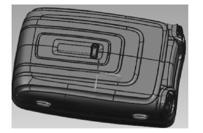
Fig. 1 Three-dimensional structure sketch of plastic parts
2 Mold design
2 Mold design
The selection of parting surface generally follows the following principles:
1 ) It is conducive to demoulding. The parting surface is generally designed at the maximum cross section of the plastic part.
2 ) help to ensure the quality of plastic parts. The selection of the parting surface should meet the surface quality requirements of the plastic parts and be conducive to the mold exhaust.
3 ) It is beneficial to simplify the mold structure, and lateral parting or core pulling should be avoided as much as possible.
4 ) Conducive to the processing of mold parts
According to the structural characteristics of the box shell, the parting surface can be divided into four types of bases
This type:
- All box shells are formed in the dynamic mold;
- All the box shells are formed in the fixed mold;
- The box shell is formed simultaneously in both the moving and fixed molds;
- The box shell is formed in multiple flap modules. The surface quality of the box shell directly determines the quality of the suitcase. Therefore, when selecting the box shell parting surface, it is necessary to ensure the surface quality and dimensional accuracy of the box shell.
For example, if scheme 2 ) is formed in the fixed mold, weld marks will appear on the surface of the box shell, and the surface quality is difficult to guarantee. If the scheme 3 ) or 4 ) is selected, there will be weld marks in each part, which also increases the processing difficulty and demoulding difficulty of the mold. Only scheme 1 ), the parting surface is designed at the maximum contour of the box shell, as shown in Fig.2.Because the bottom surface of the box shell is a plane, it is beneficial to the balance of force and demoulding, which can effectively reduce the difficulty of mold processing and ensure the surface quality of the box shell.
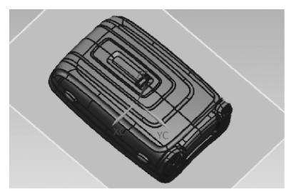
Fig.2 Parting surface schematic diagram
2.2 Cavity design
According to the structure of the box shell plastic parts, the length, width and height of the box shell are relatively large. Considering the size of the injection molding machine, the clamping force, the injection capacity and the accuracy requirements of the plastic parts, the accuracy of adding a cavity is reduced by about 4 %. If a cavity with two or more cavities is selected, the size of the mold is too large, and the difficulty of debugging is significantly increased. Therefore, the cavity design adopts the form of one mold and one cavity.
2.3 Design of gating system
The gating system is the feed channel that guides the plastic melt from the nozzle of the injection molding machine to the mold cavity. It has the functions of mass transfer, pressure transfer and heat transfer, which directly affects the overall structure, precision, difficulty of the molding process and the service life of the mold.
2.3.1 Main runner design
Considering the safety, reliability, maintenance and repair of the mold in actual use, the main runner is designed as the form of gate sleeve. According to the nozzle parameters of the injection molding machine, the radius of the nozzle ball in the main channel is designed to be 12 mm, and the diameter of the nozzle hole in the main channel is 4.5 mm. In order to reduce the pressure of the melt and reduce the loss of heat, the main channel is designed as a truncated cone.
Setting the main flow channel of the box shell at the center of the mold is conducive to evenly guiding the melt injected by the injection molding machine into the flow channel or cavity; Considering the need for the main flow channel to repeatedly contact high-temperature plastic melt and injection molding machine nozzles, the main flow channel is designed as a detachable and replaceable rubber sleeve form. The shape of the main channel of the box shell is conical, with a cone angle of 2 ° to 6 °, and the surface roughness of the inner wall is 0.63 μ M; To prevent overflow, the main channel of the box shell is designed as a hemispherical concave groove with a radius 2 mm larger than the nozzle radius of the injection molding machine, a depth of 5 mm, and a length L of 48 mm; In order to ensure the smooth extraction of the binder, the small end diameter of the main channel should be 1 mm larger than the nozzle diameter of the injection molding machine. The nozzle material of the box shell is WY718 wool, with a specification of ϕ 55 mm × 100 mm, as shown in Figure 3.
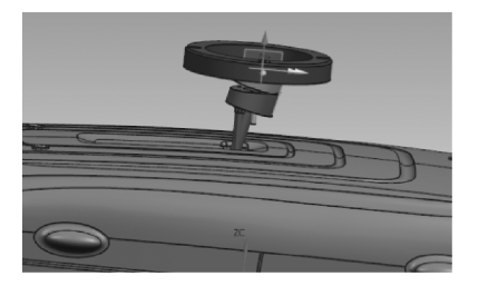
Fig.3 Main channel schematic diagram
2.3.2 Gate design
Considering the structural complexity of the plastic parts and the performance of the raw materials, the gate of the box shell is set in the middle, and the process of the plastic melt can be effectively shortened by using the direct glue mouth. The pressure loss of the melt is small, and the flow direction of the material is less, which will not produce obvious weld marks. It can effectively avoid the uneven feeding caused by the side feeding and effectively prevent the warpage deformation. At the same time, the cold material cavity is processed at the right position of the rubber mouth to prevent the cold material from entering the cavity and affecting the quality of the product.
2.4 Design of clamping guide and positioning mechanism
2.4.1 Guide pillar and guide sleeve
The guide pillar and guide sleeve are matched in pairs, generally cylindrical, and are installed on two half-molds respectively to determine the relative position of the moving and fixed molds and ensure the accuracy of mold motion guidance. The positioning and placement of the guide sleeve of the guide pillar of the mold are shown in figure 4. The guide pillar is set up with 4 pieces and placed symmetrically. The length of the working part of the guide pillar should be 8 mm higher than that of the end face of the shell core. The length of the guide pillar is 376 mm, the diameter is 60 mm, the length of the guide sleeve is 90 mm, and the outer diameter is 80 mm. The guide pillar and guide sleeve should have high hardness and wear resistance. The carbon tool steel T10A is designed to be quenched, and the hardness is more than 50 HRC.
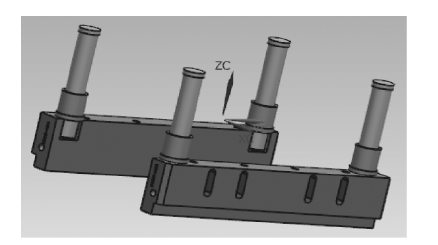
Fig.4 Schematic diagram of guide pillar and guide sleeve
2.4.2 Reset mechanism
The box shell is reset by spring. The diameter of the spring is 30 mm, and the depth of the lower template is 30 mm. The diameter of the spring hole should be greater than the diameter of the spring by 2 mm.
2.5 Cooling system design
In the process of injection molding, the mold is not only the molding equipment of plastic melt, but also plays the role of heat exchanger. The performance and molding process requirements of different plastics are different, and the requirements for mold temperature are also different. For plastics and large injection molds that require mold temperature exceeding 80 °C, heating devices need to be set up ; for plastics that require lower mold temperature, it is only necessary to set the cooling system of the mold. The shell adopts PP, and the optimum mold temperature is 40 ~ 80 °C, so there is no need to design the heating system.
The box shell die is selected to be externally connected to the direct cooling, and the water pipe joint and the rubber pipe are connected to the in-mold pipe into a single or multi-channel cycle ; the core of the box shell is relatively shallow, and the plane cooling circuit is directly set at the lower part of the core. The diameter of the cooling water channel of the core and cavity is d = 12 mm, and the cooling water flow rate is 4.33 m / s.
2.6 Design of demoulding mechanism
Because the internal precision of the shell is high, it is not a plane, and the parting surface is located at the bottom, so the thimble can not be set inside the shell. Therefore, the ejection mechanism can only be designed on the top edge, but the width of the bottom edge is very small. If a small diameter thimble is used, the top white phenomenon may occur. Therefore, the top block is selected to eject, and the top block is designed on the side of the moving die, so as to drive the demoulding device when the mold is opened and complete the demoulding. An inclined top is designed on the protruding part of one side of the box shell, which is more conducive to demoulding. In order to avoid the deformation of the product due to the unbalanced force during the push-out, eight uniformly distributed top blocks were designed. The top block size was 230 mm × 30 mm × 42 mm, and the surface of the material NAK80 was nitrided. The push rod should have sufficient strength and wear resistance. T8 carbon tool steel is selected, the hardness is more than 50 HRC, and the surface roughness is 0.8 μm. The demoulding slope is 10 °, as shown in figure 5.
.png)
Fig.5 Demoulding mechanism diagram
2.7 Mold base and material selection
Based on the size of the mold core and the injection method, taking into account the rationality, safety, and simplicity of the mold, this article chooses LongjiThe (KM) Dashuikou CH series mold base is numbered CH-6085 A-180, B-170, C-150. The upper template material is Baosteel 718H, and the lower template material is Baosteel P20. The square iron, bottom plate, ejector pin panel, and ejector pin bottom plate materials are all S50C. To ensure the strength and safety of the mold, support heads, garbage nails, and locking mechanisms are designed separately.
In summary, the structure of the complete set of molds can be obtained, and the front mold structure can be viewed asThe figure is shown in Figure 6, and the structural view of the rear mold is shown in Figure 7.
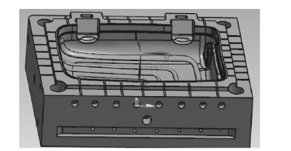
Fig. 6 Pre-mold structure view
.png)
Fig. 7 Post-mold structure view
3 Selection and check of injection molding machine
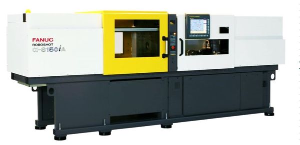
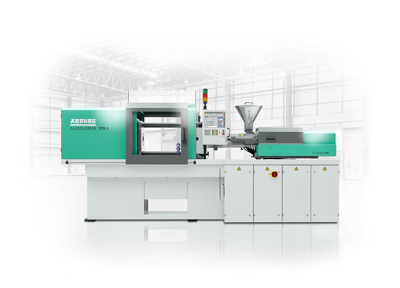
The selection of injection molding machine should take into account the size of the mold, injection volume, clamping force, opening stroke. According to the size, density and quality of the plastic parts of the case, considering the safety and reliability of the molding, SZ-160 / 1000 injection molding machine is selected. The detailed parameters are shown in Table 1.
Table 1 Parameters of injection molding machine
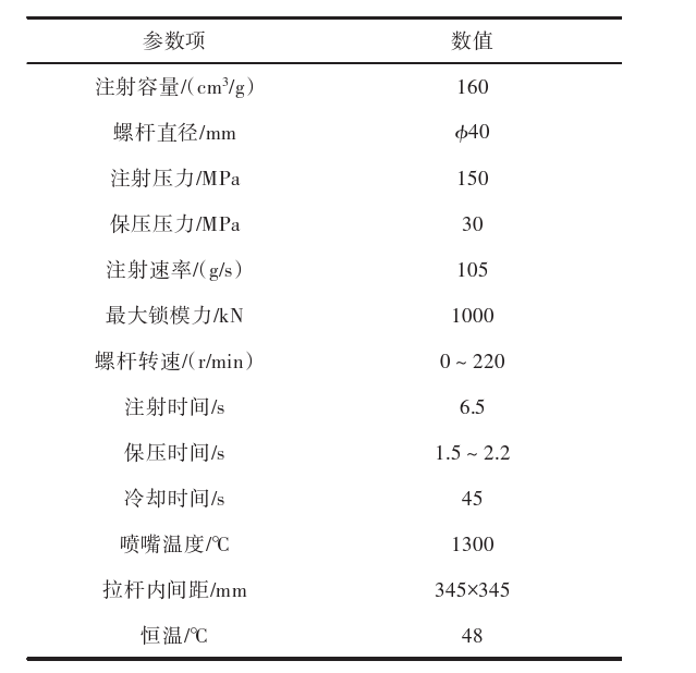
Based on the designed mold, further check the locking force, maximum injection pressure, clamping force, and opening stroke of the injection molding machine. The SZ-160/1000 injection molding machine selected is fully matched with the designed mold and meets production requirements.
4 Mold design innovation points
In summary, the designed mold has a simple structure, no need for manual cutting during the production process, fast production speed, high degree of automation, and can effectively reduce labor costs; The mold manufacturing process is simple, the appearance of the parts is good, and the service life is long, suitable for large-scale production by enterprises. The innovative design points of this mold include: 1) adopting a parting surface design where the products are fully formed in the dynamic mold, effectively improving the quality of product molding. 2) A cold material hole is designed in the position directly opposite the rubber mouth, which can effectively prevent cold materials from entering the mold cavity and improve product quality. 3) Designed 8 evenly distributed top blocks and a sloping top demolding mechanism. 4) Design exhaust grooves around the mold cavity, utilizing the parting surface, push rod clearance, and core insert clearance for exhaust, which not only reduces mold processing costs but also ensures the quality of the plastic parts.
5 Conclusion
Aiming at the appearance, process and performance requirements of the pull rod box, based on the analysis of the three-dimensional structure and material of the pull rod box shell, according to the structural characteristics and injection molding of the product, the parting surface of the box shell formed in the moving mold is designed. Based on the mold structure of one mold and one cavity, the main channel and gate, guide pillar and guide sleeve, reset mechanism, cooling system and demoulding mechanism of the full set of mold for the box shell are reconstructed and designed. According to this, the mold base and materials of the CH series of Longji ( KM ) large nozzle are selected. Finally, the injection molding machine is selected and checked. It has been verified that the mold structure is reasonable, the movement of each component is smooth and reliable, the injection molding effect is good, and the product molding quality is good.
1. FAQ: What are injection molds used for in manufacturing?
- Answer: Injection molds are crucial tools in manufacturing that shape molten material, often plastics, into various products like automotive parts, packaging containers, and consumer goods.
2. FAQ: What factors influence the cost of an injection mold?
- Answer: The complexity of the design, material selection, size, and production volume impact mold costs. Precision molds for intricate designs or large-scale production tend to be more expensive.
3. FAQ: How does the injection molding process work?
- Answer: Injection molding involves injecting molten material into a mold cavity. The material cools and solidifies, taking the shape of the mold. It's a versatile and efficient method for mass production.
4. FAQ: What's the difference between single-cavity and multi-cavity molds?
- Answer: Single-cavity molds produce one part per cycle, suitable for low-volume production. Multi-cavity molds create multiple identical parts in each cycle, optimizing production rates for high-volume needs.
5. FAQ: What are the benefits of using precision injection molds?
- Answer: Precision molds ensure consistent, high-quality parts with tight tolerances. They reduce material waste, post-processing, and assembly requirements, leading to cost savings and better end products.
Get Quote
- Visit our website: https://www.nbyichou.com/
- Email us: [email protected]
- Call us/whatsapp: +86 13355741031
- Chat with us: Live chat support available on our website