Target Audience: Mechanical Engineers, Product Designers, Procurement Managers, Hardware Startup Founders
Primary Keywords: sheet metal design for manufacturability, sheet metal DFM tips, reduce sheet metal fabrication cost
Secondary Keywords: sheet metal bend radius, minimum hole to edge distance, sheet metal cost reduction, custom sheet metal fabrication, precision sheet metal design
Introduction: When a Perfect CAD Model Meets an Imperfect Shop Floor
Your 3D model is clean. The tolerances are tight. The assembly fits together perfectly on screen. Then the quote comes back — 40% over budget — and your fabricator flags three features as “not manufacturable” before the file even reaches the laser cutter.
This gap between digital design and physical production is where sheet metal budgets die. Strategic planning during design shapes approximately 70% of manufacturing expenses in sheet metal fabrication, meaning the decisions you make in the first 72 hours of a project determine whether you pay $2.40 or $4.80 per bracket. That difference compounds across thousands of units.
Design for Manufacturability (DFM) is the discipline that closes this gap. It is a strategic approach that integrates manufacturing considerations into the design process, ensuring products are easier and more cost-effective to produce. When applied to sheet metal, DFM principles can reduce manufacturing costs by 20–50% without compromising part quality or functionality.
This guide moves beyond surface-level advice. Each section addresses a high-frequency search query from engineers and procurement teams — bend radius standardization, hole placement rules, weld minimization, tolerance strategy, and material gauge selection — with specific numbers, cost mechanics, and implementation guidance you can apply to your next design.
Tip 1: Standardize Bend Radii Across Your Design
Why This Is the #1 DFM Lever
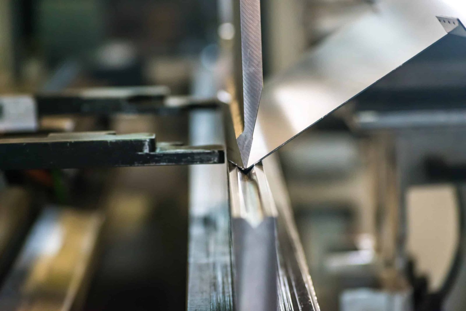
Using multiple inside bend radii on a single part — say 1.5mm, 2.0mm, and 3.0mm — forces your fabricator to perform frequent tool setups on the CNC press brake. Each tool change adds setup time, and non-standard radii may require custom tooling that drives up both cost and lead time.
Standardized bend radii that match press-brake tooling remove specialty tooling orders and extra setups, which cuts cost and lead time. The internal bend radius should ideally match the material thickness (R = T). For mild steel (SPCC) up to 3mm thick, 1× material thickness is the standard. For thicker stock or high-strength materials like stainless steel (SUS304/316L), 1.5× thickness or greater is recommended.
Material-Specific Bend Radius Limits
Different alloys have different formability limits. If the bend radius is smaller than the minimum, the outer surface will crack.
| Material | Recommended Min. Inside Radius |
|---|---|
| Low-Carbon Steel (A36, 1018) | 1T |
| Stainless Steel (SUS304) | 1T–1.5T |
| Aluminum 5052-H32 | 1T |
| Aluminum 6061-T6 | 2T–3T |
(T = material thickness)
Harder alloys such as 6061-T6 aluminum typically require 3T–4T to avoid cracking. Additionally, orient bend lines perpendicular to the material grain direction whenever possible, as bending parallel to the grain increases crack risk, especially for low-ductility alloys.
How It Saves Cost
Eliminating tool changes directly reduces machine setup time, which is pure non-productive time. When all bends share the same radius, the operator can complete multiple bends without swapping punches or dies. This improves throughput consistency and reduces the risk of dimensional drift between parts in a batch.
Pro tip: Whenever possible, align all bends in the same direction to further minimize tool changes during production.
.jpg)
Tip 2: Maintain Safe Distances Between Holes, Slots, and Bends
The Most Common DFM Failure Point
Holes placed too close to a bend line or edge will distort, stretch, or crack during the press brake folding process. If a hole is located within the bend's deformation zone, it can stretch into an oval shape, causing assembly failures and requiring secondary reaming or drilling to correct. In sheet metal bending and forming, warping, localized distortion, and corner tearing are common manufacturing defects that stem directly from inadequate feature clearance.
The Clearance Rules That Matter
Hole-to-bend distance: Maintain at least 3× material thickness + bend radius (3T + R) from the bend line. The minimum acceptable distance is 2T + R, but 3T + R is the recommended value for reliable results. For holes larger than 25mm in diameter, increase this distance further.
Hole-to-edge distance: Keep at least 2× material thickness (2T) from any edge. Alternatively, keep holes at least 1× their diameter from an edge.
Slot-to-bend distance: Slots are more vulnerable to distortion than circular holes. Maintain at least 4T + R from the bend line.
Hole-to-hole spacing: Keep at least 1× material thickness between adjacent holes, with 2T recommended for optimal reliability.
| Feature Relationship | Minimum | Recommended |
|---|---|---|
| Hole edge to bend line | 2T + R | 3T + R |
| Slot edge to bend line | 3T + R | 4T + R |
| Hole to hole spacing | T | 2T |
| Hole to edge distance | T | 2T |
| Min. hole diameter | T | 1.5T |
The Bend Relief Solution
When two bends intersect, material accumulates in the corner and creates an uncontrolled bulge that shifts adjacent feature positions. The fix is a bend relief — a small notch or slit at the intersection point. The relief width should be ≥ material thickness, and the depth should be ≥ bend radius + material thickness. Relief cuts should be at least 0.010 inches (0.25mm) or 1× material thickness, whichever is greater.
How It Saves Cost
Following these clearance rules avoids secondary reaming, drilling, or manual deburring after bending to correct deformed holes. Each secondary operation adds labor cost and risk of introducing new defects. In high-volume production, even a 2–3% scrap rate reduction translates to significant annual savings.
Tip 3: Avoid Over-Welding & Optimize Joint Configurations
Why Welding Is Your Most Expensive Operation
Excessive TIG/MIG welding and full-seam welds increase thermal distortion and require labor-intensive manual grinding and finishing. Welding is typically the most expensive operation in sheet metal fabrication — both in terms of skilled labor hours and post-weld processing. When steel sheets cool down after welding, non-uniform temperature distribution causes deformation, and correcting this distortion adds cost at every stage.
Most sheet metal cost comes from material waste (poor nesting), expensive secondary operations like welding and powder coating, and oversized tooling.
DFM Strategies for Weld Reduction
1. Use tab-and-slot (interlocking) designs. These features allow parts to align themselves during assembly, eliminating dedicated fixtures and reducing setup time. The tab-and-slot approach also distributes welding stress more evenly across the joint. One documented case showed that switching from continuous welds to tab-and-slot self-locating with intermittent welding reduced flatness deviation from 2.5mm to ≤0.4mm.
2. Replace continuous welds with stitch or tack welding where structural strength allows. Full-seam welds are only necessary for pressure-tight joints or high-load structural connections. For most enclosure panels, brackets, and frames, intermittent stitch welds provide sufficient strength with dramatically less heat input and distortion.
3. Incorporate stress-relief slots in non-load-bearing areas adjacent to welds to block thermal stress propagation across large flat surfaces.
4. Plan weld seam locations during the design phase. To minimize post-weld distortion, plan weld seam locations and joint sequences during the design phase rather than after.
How It Saves Cost
Reducing weld volume drastically cuts skilled welder labor hours and post-weld surface grinding. In practical terms, a full-seam weld on a 300mm joint might take 8–10 minutes of welding plus 15–20 minutes of grinding. A stitch weld on the same joint takes 2–3 minutes of welding with minimal finishing required. Across a production run of hundreds or thousands of parts, this difference compounds into substantial labor savings.
Tip 4: Be Strategic with Tolerances (Avoid “Over-Engineering”)
The Hidden Cost of Overly Tight Tolerances
Specifying tolerances like ±0.05mm on non-critical dimensions — outer cover panels, cosmetic surfaces, non-mating edges — needlessly inflates scrap rates and inspection time. Sheet metal fabrication has wider dimensional variances compared to CNC machining due to the nature of the forming process. Overly strict tolerances increase manufacturing difficulty, leading to higher costs and longer lead times.
What Standard Tolerances Actually Look Like
For typical sheet metal parts using laser cutting and CNC bending:
| Process | Standard Tolerance |
|---|---|
| Laser cutting — length | ±0.2 ~ ±0.5mm |
| Laser cutting — hole diameter | ±0.08 ~ ±0.12mm |
| Bending angle | ±0.5° ~ ±1.0° |
These are governed by standards like ISO 2768-m, which applies specifically to sheet metal workpieces.
The DFM Rule
Reserve tight tolerances only for critical mating features such as shaft bores, mounting hole patterns, and alignment-critical edges. Apply standard sheet metal tolerances (ISO 2768-m or equivalent) elsewhere.
When designing based on outer dimensions, remember that final edge measurements may vary due to angular tolerances. Always account for cumulative tolerances and provide sufficient clearance.
The Tolerance Cost Multiplier
Tolerances function as a cost multiplier in sheet metal fabrication. Moving from standard (±0.5mm) to precision (±0.1mm) can increase per-part cost by 30–60%, while ultra-precision (±0.02mm) can double or triple it. For parts requiring high-precision assembly, consider secondary CNC machining (post-processing) after sheet metal fabrication rather than tightening tolerances across the entire part.
How It Saves Cost
Relaxing non-critical tolerances lowers rejection rates, cuts CMM (Coordinate Measuring Machine) inspection time, and avoids expensive precision machining operations. A part that would require 15 minutes of CMM inspection with tight tolerances might need only 3 minutes with standard tolerances — a direct reduction in quality-control costs.
.jpg)
Tip 5: Choose Standard Material Gauges and Stock Sizes
Why Non-Standard Thicknesses Destroy Your Budget
Specifying custom sheet thicknesses — for example, 1.8mm stainless steel instead of standard 1.5mm or 2.0mm — leads to long material lead times, higher raw material costs, and increased scrap. Non-standard gauges often require special mill orders with minimum quantities that far exceed your actual project needs.
Standard gauge materials often cost less than custom thicknesses, which require special ordering, minimum order quantities, and longer delivery times.
Standard Gauge Reference Table
| Gauge | Thickness (mm) | Thickness (in.) | Common Applications |
|---|---|---|---|
| 20 | 0.91 | 0.036 | Enclosures, light brackets |
| 18 | 1.22 | 0.048 | General brackets, panels |
| 16 | 1.52 | 0.060 | Structural brackets |
| 14 | 1.90 | 0.075 | Heavy-duty frames |
| 12 | 2.78 | 0.109 | Load-bearing components |
Material Cost Comparison (2026)
Raw material pricing varies significantly by alloy and gauge. Aluminum sheet ranges from roughly $4.50 to $11.00 per square foot for common 1/8-inch thickness, while galvanized sheet steel was priced at approximately $57 per hundredweight in March 2026.
| Material | Approx. Cost/unit weight | Relative Cost |
|---|---|---|
| Mild Steel (SPCC) | ¥5–8/kg | Baseline |
| Stainless Steel (304) | ¥18–25/kg | 3–4× |
| Aluminum (5052) | ¥20–28/kg | 3–5× |
(Market pricing data from 2025, China market)
The Nesting Factor
Material utilization (nesting efficiency) is invisible in CAD but dominates sheet metal cost. Poor nesting can add 30–50% to material expense. When nesting multiple parts on a standard sheet, keep hole and slot placements consistent across part families so the fabricator can optimize material utilization without re-programming every job.
How It Saves Cost
Standard gauges capitalize on lower bulk material purchasing prices and minimize raw material scrap. Fabricators can batch similar orders together on the laser cutter, efficiently reuse remnant sheet material across jobs, and avoid the lead-time penalties of special mill orders. Using standard gauges reduces material costs by 15–25% compared to non-standard thicknesses.
Additional High-Impact DFM Considerations
Surface Finish Selection: The Invisible Cost Driver
Surface finishing is one of the most overlooked cost drivers in sheet metal design. The most expensive finish is the one you apply unnecessarily. Here is a practical cost comparison for common finishes:
| Finish | Typical Cost (per medium part, 100 pcs) | Lead Time Impact |
|---|---|---|
| As-machined (no finish) | $0 | None |
| Zinc Plating | $3–6 | +2–3 days |
| Powder Coating | $5–10 | +3–5 days |
| Anodizing Type II | $4–8 | +3–5 days |
| Hardcoat Anodize | $15–25+ | +5–7 days |
(Based on 1.5mm steel/aluminum parts)
Most coating shops have a minimum lot charge of $80–150 regardless of part quantity, so batching finishes across part families can dramatically reduce per-unit costs. For high-production volume runs, powder coating is almost always the cheapest per-unit option while still delivering excellent corrosion and chemical resistance.
DFM rule: Specify the finish based on the operating environment, not on aesthetics alone. For indoor enclosures, zinc plating or black oxide may suffice. For outdoor or high-corrosion environments, powder coating or anodizing justifies the additional cost.
Prototype vs. Production: Different DFM Priorities
The DFM rules that apply to production volumes don't always apply to prototypes. For prototype and low-volume runs, the priority is speed and design validation, not per-unit cost minimization.
Prototype-specific cost levers:
-
Replace progressive dies with CNC laser cutting and simple air bending to reduce initial prototyping setup costs by up to 80% for low-volume verification runs.
-
Laser cutting combined with CNC press brake air bending is the fastest and most cost-effective custom sheet metal fabrication method for rapid prototyping.
-
Choose the cheapest material that meets functional requirements for prototypes — the material grade that will be used in production can be validated separately.
Production-specific cost levers:
-
Tooling amortization becomes viable above certain volume thresholds. One documented case showed a client cutting costs from $4.20 to $1.25 per part using stamping at volume.
-
Consolidate multiple fabricated parts into fewer, more complex parts to reduce assembly labor.
Process Selection: Laser Cutting vs. Stamping vs. CNC Punching
Choosing the right cutting process is a DFM decision with major cost implications:
| Process | Upfront Tooling | Best Volume | Shop Rate (US) |
|---|---|---|---|
| Fiber Laser Cutting | $0 | 1–10,000 units | $80–180/hr |
| CNC Turret Punching | Low | 100–50,000 units | $90–120/hr |
| Stamping | $3,000–$30,000+ | 10,000+ units | $80/hr |
(Shop rate data from 2026 US pricing guides)
Fiber laser cutting with CNC press brake bending is virtually always the most economical strategy for low-to-mid volumes due to zero die expenditure. The decision to move to stamping should be driven by volume calculations, not by assumptions about “production efficiency.”
Summary & Pre-Submission DFM Checklist
Before you submit your next CAD file for RFQ, run through this checklist:
| ✓ | DFM Check | Rule |
|---|---|---|
| ☐ | Uniform bend radius applied? | R = T (1× material thickness) |
| ☐ | Bend lines perpendicular to grain direction? | Critical for low-ductility alloys |
| ☐ | Hole-to-bend clearance checked? | ≥ 3T + R recommended |
| ☐ | Hole-to-edge distance verified? | ≥ 2T from any edge |
| ☐ | Bend reliefs added at intersecting bends? | Width ≥ T, depth ≥ R + T |
| ☐ | Tab-and-slot features utilized for assembly? | Replaces fixtures, reduces weld volume |
| ☐ | Weld seams minimized? | Stitch/tack welds where possible |
| ☐ | Non-critical tolerances relaxed? | ISO 2768-m standard |
| ☐ | Standard sheet gauges selected? | Avoid custom thicknesses |
| ☐ | Surface finish specified only where needed? | Match finish to operating environment |
| ☐ | Process selected based on volume? | Laser + bending for < 10,000 units |
Each of these checks addresses a specific cost driver in sheet metal fabrication. Applied together, they form a design philosophy that consistently produces lower quotes, faster lead times, and fewer production surprises.
Ready to Optimize Your Sheet Metal Parts for Production?
our engineering team provides complimentary DFM analysis for every project. Upload your 3D CAD files (STEP / IGES / DXF) today to receive a competitive quote and expert design feedback within 24 hours.
Whether you're prototyping a single enclosure or scaling to high-volume production, our team will review your design against real manufacturing constraints — bend radii, hole clearances, weld optimization, tolerance strategy, material selection, and surface finish — and suggest specific changes that reduce cost without sacrificing quality.
[Request a Free DFM Review & Quote →]
No commitment required. Upload your files, get actionable feedback, and see exactly where your design can save money.
Get Your Custom Quote Today
- Contact Us: Share your project details with our experienced team, and let us provide tailored solutions for your unique needs.
- Fast & Competitive Pricing: Receive a detailed quote quickly, ensuring your project stays on track.
- Reach Out Anytime:
- Email: [email protected]
- Call/WhatsApp: +86 13355741031
- Live Chat: Connect with our support team instantly via our website's chat feature