Abstract:This paper discusses the precision machining technology of several typical parts used in aerospace in Europe and America, including the primary mirror development of American space telescope, the precision machining of the combustion chamber regenerative cooling channel of rocket engine and the high-speed milling of the isogrid of large rocket panels. It can be seen from these typical examples of precision machining that precision machining technology has been progressing with the development of the aerospace industry and has always occupied an important position in the development of aerospace products.
Key words:precision machining;mirror processing;space telescope;cooling channel;isogrid
1 Introduction
With the development of space product serialization, standardization, space parts development and production of size precision, processing efficiency and surface integrity is more and more high, many parts need precision manufacturing: such as large mirror precision grinding and polishing technology, rocket engine cold, but channel molding and rocket tank grid processing, etc., need to be accurately and efficiently. With the development of materials and digital technology, the precision machining technology has been further updated. Precision machining technology comprehensively applies the new achievements of the development of mechanical technology and modern electronics, sensing technology, technology, optics and computer and other high and new technologies, which is an important embodiment of a country's science and technology, level and comprehensive national strength, so it is highly valued by the industrial developed countries.
2 Mirror surface precision machining technology
In the past fifty years, the diameter of traditional astronomical instruments has expanded from the 2m level to the 10m level. In addition to the development and progress in material applications, their mirror precision machining technology has also been a focus of research. The Hubble Space Telescope (HST), which was launched into orbit by the US space shuttle in 1990, and the James Webb Space Telescope (JWST), which will be put into use in 2021, both use computer controlled tool ejection (CCOS) technology to manufacture their main mirror segments, but the materials and processes have undergone changes. The advanced technology for precision machining of mirrors also includes the stress disk polishing technology used by the Steward Observatory's large-sized lens laboratory at the University of Arizona in the United States, as well as the CNC ion beam polishing method used by the Keck telescope after stress machining.
2.1 Development of the Hubble Space Telescope
The Hubble telescope, jointly developed by NASA and ESA), is named after renowned American astronomer Edwin Powell Hubble. Development began in 1978 and was originally scheduled to be launched in 1983, but the project was not completed until 1985. On April 25,1990, the Space shuttle Discovery sent the Hubble telescope into space. Hubble was designed to collect data for 15 years and has been in service after five repairs. NASA had planned to retire after the Hubble telescope with shuttle back, as a museum exhibits, then change plan: the last time in 2009 maintenance, in addition to install upgrade device security telescope free rotation, also equipped with a small propulsion device, make the Hubble telescope in retirement controlled into the atmosphere destroyed. The Webb telescope, which replaced Hubble, was originally scheduled to launch in 2014, but has since been delayed until 2021. During its 28 years of operation, the Hubble telescope has helped astronomers make many groundbreaking discoveries and capture countless stunning optical images of the universe.
The Hubble project is divided into many sub-projects, with the Marshall Space Flight Center (MSFC) responsible for the design and manufacture of the telescope, and its optical systems and guidance sensors subcontracted to Perkin Elmer (Perkin Elmer). The Hubble telescope is 13.2m long, weighs 11t, and has a maximum diameter of 4.2m. The main mirror grinding undertaken by Perkin Elmer is the most critical part of the telescope. The main mirror of the telescope is polished at one-twentieth of the visible wavelength, or about 30nm. To achieve such demanding precision requirements, Perkin Elmer plans to grind the main mirror into the desired shape using a special, advanced-computer-controlled polishing machine. To prevent problems with Perkin Elmer's cutting-edge technology and affecting the Hubble telescope, NASA asked to subcontract to Kodak to build a backup mirror with traditional mirror polishing technology. The main mirror produced by Perkin Elmer was launched, and the standby main mirror produced by Kodak was sent to the National Aerospace Museum for permanent display.
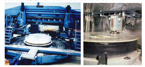
Figure 1 Processing and detection of the Hubble Telescope master mirror
Hubble Telescope Main Mirror Φ 2.4m, weighing 828kg, made of ultra-low expansion glass. Perkin Elmer first developed an extremely complex computer-controlled polishing machine at the time, and also developed supporting polishing detection technology. The development of the primary mirror is often carried out at night, as the vibration generated by vehicle operation can affect the accuracy of the equipment. In order to reduce weight, the middle of the main mirror is processed into a honeycomb shape, and the upper and lower sides are sealed with 25mm thick glass. At the end of 1981, the three-year development work was finally completed, and a 75nm thick aluminum reflective layer and a 25nm thick magnesium fluoride protective layer were plated on the mirror surface. Figure 1 shows the processing and inspection of the main mirror of the Hubble Telescope.
The main mirror is perfectly polished, perfectly symmetrical, but beyond the budget and beyond the deadline for the development cycle. NASA hastily ended the project, but sadly found that the reflective zero corrector system designed to measure the polishing work had a 1.3mm deviation, resulting in a slight aberration of the main mirror, leaving the initial work out of focus, and the images sent back blurred. NASA blamed the lack of quality control for making the main mirror, and Perkin Elmer complained that NASA finished the project in a hurry to give enough time to complete the quality control work, resulting in a final test that should have cost $10 million and $2 billion to repair. Fortunately, Perkin Elmer's main mirror is perfect, so it's quite easy to repair.
The backup mirror for the Hubble main mirror is made by Kodak, including grinding, spherical repairing, polishing and testing. The main mirror blank with a thickness of 300mm is Corning glass, which consists of 25mm thick two glass clips with glass honeycomb, which is 5 times lighter than the solid plate material. When processing, place the blank on the large grinding machine with special steel cutting tools, first cut the front and back of the blank into spherical and round, and then grind the slope and polish the edge of inner and outer diameter to achieve the weight reduction; then place the lens on the large loose abrasive bed for grinding and grinding the ball surface. This process can remove about 0.762mm thick material; When the mirror surface contains 1.3 µ m of the required surface, grind the mirror plate into a highlight area.
In the early 1980s, the optical manufacturing in the United States mainly relied on the extraordinary manual polishing technology of highly skilled matching goggles, and now it is all used, advanced computer numerical control equipment, using technology such as high pressure water cutting and ion grinding process.
2.2 Precision machining of the James Webb Space Telescope mirror
The Weber telescope is a new generation of large space telescopes to replace the retiring Hubble telescope. The Weber telescope, developed by NASA, ESA and the Canadian Space Agency (CSA), was scheduled to be launched in 2014, but was delayed due to budget and a series of technical issues, and is now expected to be launched into space in 2021.
The Weber telescope is not equipped with a tube and weighs 6.2 tons. The main mirror of the Weber telescope Φ 6.5m, compared to the Hubble telescope, it has a larger diameter, 2.5 times that of Hubble, and a surface area 6 times larger than Hubble; The equipment is more precise, and the infrared spectral sensitivity is 1000 times higher than the original; The most crucial thing is that the Weber telescope uses ultra-thin and ultra-light lenses, which greatly reduces the total weight of its main mirror, about 705kg. Due to the large size of the lens, it is necessary to fold the lens during launch. Therefore, the main lens of the Weber telescope is designed as a series of hexagonal split lenses. Unlike the Hubble telescope, the Weber telescope does not orbit over Earth, but is directly launched into space 1.5 million kilometers away from Earth, flying at the position of the second Lagrange point (L2). Due to its distance from Earth, it is not possible to send astronauts for maintenance and repair, so the Weber telescope must be manufactured flawlessly, which is also one of the reasons for repeated delays in launch. The project has been repeatedly postponed, resulting in a significant increase in its costs.
The Weber telescope was developed by Norge (Northrop Grumman), including the processing of the main mirror, the most important part of the telescope. The main mirror consists of 18 hexagonal sub-mirrors with folded emission, tuned open in orbit. The mirror is refined from the largest lightweight beryllium fiber. Beryllium fiber material is light in weight and high in hardness, and can withstand huge temperature changes without warping, and this material is very stable for temperature changes in the range of 30 to 80 K. The manufacturing of each submirror section includes processing, heat treatment, inspection, coating and polishing of the mirror.
Mirror processing is carried out in the temperature control plant. The processing equipment is 8 horizontal machining centers customized by Mitsui Precision USA, and the positioning and travel accuracy of the equipment can reach several microns. Processing includes:
- Installation of beryllium billet. About 245kg beryllium billet is mounted vertically on the angle plate of the machine tool;
- Process the shape of the submirror. Size is 101.6mm thick, span of 1.37m, point to point of the hexagonal type of 1.57m;
- Grid machining. On the back of each submirror, 600 grids of the 16.13cm2, as shown in Figure 2. Weight of the sub-mirror is reduced to 125kg;
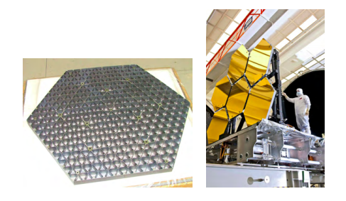
Figure 2 Grid and mirror assembly diagram on the back of the six sides
- Processing and installation pads, etc. The position of 22 mounting pads on the submirror;
- Heat treatment to remove machining stress;
- rough machining of the mirror.23-27 kg;
- inner inner inner mesh. The mesh wall thickness is 0.51~7.59mm;
- Mirror side, grid side and positioning hub, the finishing tolerance is generally 0.000~0.005mm.
Finally coated with a gold layer. The thickness of the gold coating is only 120nm, covering about 3.4g of gold, which provides a high reflectivity from 0.6 to 28 μ m. When coating the mirror, the gold needs to be heated to 1371℃, melted from the solid to the liquid, and then evaporated to the beryllium plate to form a smooth, microscopic, visible thin coating. From June 2010 to September 2011, Nog completed the Weber telescope mirror gilding work. The coating project is the latest high technology of the main mirror, facing many technical challenges. The completion of the project has made the development of the main mirror make great progress.
The fine grinding and polishing are performed in a computer-controlled optical surface manufacturing equipment (CCOS), using a coordinate measuring machine (CMM) to detect the accuracy of part size and residual stress. For mirror processing, the most important thing is precision, not speed. The accuracy of the machine tool is the basis of precision machining. When the mirror machining equipment is placed, it is necessary to pad a 990.6mm thick concrete plate under the equipment, surrounded by sand beds, to isolate the vibration generated by the surrounding equipment. Each machine tool is fixed with 27 foundation disks, and each plate is fixed with 4 anchor bolts. Mirror assembly requirements should be carried out in a strictly controlled clean room, and the work clothes, hats and masks of the assembly personnel should also be strictly regulated.
2.3 New polishing technology for optical instruments of the future Giant Telescope (ELT)
At present, the international community pays great attention to the development technology of 30~100m, giant telescope. California 30m telescope (CELT) main mirror by 1080 pieces of 1m long hexagonal off-axis aspheric, using the processing method of the main mirror of the round mirror advance stress deformation, then, processing into a sphere, release the prestressed after aspherical, then cut into hexagonal, then using ion bombardment to eliminate the edge deformation caused by cutting. The use of active optical disc throwing technology can directly process the hexagonal off-axis aspherical surface, without cutting and ion beam modification. The active off-axis aspheric experiment conducted by the Mirror Lab laboratory of the Steward Observatory in the United States has played a key role in the optical processing of the next generation of telescopes.
Traditional astronomical instruments are mostly made of metal and glass. Finite element modeling (FEM), lightweight technology, clever optical design, and effective control have expanded the telescope's instruments from the 2m level to the 10m level, but there are no significant modifications in the manufacturing materials. Over time, the Extremely Large Telescope ELT will become heavy and difficult to control and move. In addition, due to the fact that many of the instruments that currently make up ELT are composed of the same subsystems, the requirements for optical components have shifted from "perfect single piece" to "acceptable series production". Materials such as polymer compounds, composite materials, light metals, and functional alloys may also gradually enter the design considerations of astronomical instruments. Correspondingly, new processes such as ion beam polishing and holography will gradually replace traditional manufacturing techniques.
Future ELT focal plane instruments composed of different materials may be large optical surfaces with an aspheric shape, with extremely strict tolerance requirements, difficult and expensive to manufacture. The Ion beam grinding (Ion Beam Figuring-IBF) process proved to be the most effective high-precision grinding technique. This non-contact polishing process has the characteristics of high processing accuracy, no stress, clean and pollution-free processing surface, especially suitable for processing spherical mirror, hexagonal mirror, etc. Because ion beam polishing is to realize the removal of materials in atomic order, the removal efficiency is low, so the traditional method is usually used to pre-polish the workpiece, and after the basic accuracy requirements, the ion beam polishing is used to correct the spherical, aspherical or asymmetric free surface with high precision. The ion beam polishing process requires large equipment investment and high operation cost, but it is essential for some large optical mirror processing with special high precision requirements. ELT optical components are processed in this way, that is, the first traditional polishing, and finally with IBF milling and grinding.
3 Precision machining technology of cooling channel of engine combustion chamber
Burning chamber is the core component of liquid rocket engine, coupled with the harsh working environment, so it is necessary to choose the materials with good thermal conductivity and high heat resistance. Initially, the liquid rocket engine combustion chamber was made of steel wall sandwich structure, which is complex and bulky, with low sandwich stiffness and low pressure capacity, and is easy to be damaged during manufacturing and commissioning. Germany took the lead in developing heat conduction materials for thin-walled combustion chamber lining, such as aluminum and copper. Since then, the United States for company developed Narlay-Z copper alloy for the space shuttle main engine (SSME) combustion chamber, and the Russian RD-0120 hydrogen oxygen engine main combustion chamber using the chromium bronze alloy material lining, European room (Astrium) company in ali Ann 5 main engine vulcan combustion chamber accordingly used copper alloy CuAgZr material.
The combustion chamber structure is also constantly innovated, from the original corrugated plate sandwich structure to milling groove. At present, the milling groove structure used in the combustion chamber of the main foreign hydrogen and oxygen engines is the cooling channel on the outer surface of the copper alloy in the inner wall of the combustion chamber, and then the sealing of the cooling channel. In the processing of the cooling channel, the precision processing process has always played an important role, but also maintains the position of one of the core production processes in the space field. Due to the high processing accuracy requirements of the combustion chamber profile and its cooling channel, the processing materials are constantly updated, ensuring the processing quality while reducing the cost and saving the manufacturing time. Therefore, to optimize the combustion chamber processing process, the evoa engine combustion chamber manufacturer Astrium company carried out special topic "high performance processing (HPC), namely, precision, materials and processing time to achieve the highest requirements", specializing in the engine combustion chamber, processing problems, and therefore introduced a processing center, to meet ali Ann 5 core engine "vulcan 2" and new engine "Mr Vinci" thrust chamber development.
The processing of the outline of the combustion chamber does not allow the form of steps, and the processing can only be processed from both sides of the fine car, or through the special vibration-free installation. The cooling channel is also very difficult to process. Take the upper stage engine "Vinci" under development as an example, the combustion chamber lining material is CuAgZr, the cooling channel on the outer surface of the lining is 468, the cold near the throat, but the narrowest part of the channel is only 0.7mm wide, the thinnest part of the inner wall is less than 0.6mm. The geometry of the cooling channel is also curved in addition to the straight groove. Astrium The company used its special 0.7mm thick disc thin milling cutter to process the straight groove section, and modified the tool to process the U and S groove sections, as shown in Figure 3. Special clamp clamps are used to ensure the low vibration environment of the milling process and the rigidity of the tool. High speed milling spindle speed can reach 2000r / min, which is 10 times of traditional processing parameters.
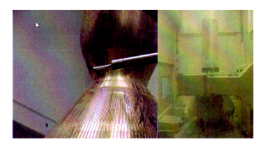
- Processing and on-line measurement of the cooling channels

- A carbide disc milling cutter
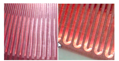
- S and U cooling channels
Fig. 3 Milling and detection of the filament cooling channel in the combustion chamber
Because the surface quality of the cooling channel wall is crucial to the cooling of the combustion chamber, in addition to check the surface roughness of the channel, in the process of high precision milling, the online measurement, and the processing results are fed back to the machine control system to correct the parameter control in the milling process and optimize the milling effect. The results of this project save 50% of the engine combustion chamber processing cost, 50% of more than 50% of the time saving, and the quality of the parts is also improved.
4 High-speed milling technology of the tank wall plate grid
The carrier rocket tank belongs to the large thin-walled structure, and the forming quality directly affects the bearing capacity of the tank. For the purpose of weight reduction, there are a large number of weight reduction grids distributed on the inner surface of the tank and the outer surface of the upper and lower bottom panels. The processing accuracy of the grid is related to the overall strength and weight reduction effect of the tank. Therefore, the size tolerance of the grid is strict. The early grid processing mainly uses chemical milling, the grid wall thickness of the milling is uneven, the root corner is large, the parts are heavy, and the milling process is polluting, does not meet the requirements of environmental protection. Therefore, the high-speed CNC milling green and efficient production process is now used, and the processed grid size, with high precision and small residual weight, can effectively increase the load of the rocket.
In the 1990s, the United States began to develop a large carrier rocket Del 4. The diameter of the tank increased from 3m class to 5m class, and the processing capacity of the wall grid increased a lot. The processing speed and size requirements of the numerical control imitation milling process used in the past could not meet the production requirements of Del 4. In order to improve the production efficiency, the multi-axis and high-speed new spindle is specially developed for the processing of del it 4 wall panels. The new spindle weighs 443kg and consists of 5 gear drive heads, as shown in Figure 4. In the five-axis device, the central axis rotates at a speed of 7200r / min, driving four trajectory axes, and the maximum speed is up to 10000r / min. The new spindle is installed on the Cincinnati machine tool in the United States, and some new equipment is concentrated in Boeing's new plant in Decatur, mainly for efficient milling of aluminum grids. The del-4 tank weight loss grid is a triangle of different dimensions. When machining, the aluminum plate is adsorbed on the vacuum suction cup for end surface milling; then replace the tool for grid milling, namely 4 tools, 3 axes and 4 grooves, rough milling, working power up to 73.5kw; finally process the grid to the specified size with the finishing tool. The siding processing process of del 4 can remove 60%~70% of raw materials, and the CNC dividing device of the machine tool can realize the unloading of parts at the same time in the processing process, which further improves the processing efficiency of the system and shortens the processing time by 40%.
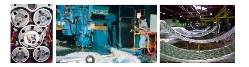
Figure 4. Processing of Zagar spindle head and tank wall plate
The heavy carrier Space Launch System (SLS), which is currently being developed in the United States, has a tank diameter of 8m, a larger milling amount of the panel mesh, and the accumulation of grid errors can seriously affect the weight of the load. AMRO Manufacturing Company (AMRO Fabricating Corporation), which is responsible for the processing of SLS tank panels, successfully formed and processed the tank panel with advanced processing and testing technology, as shown in Figure 5. The SLS tank is made of aluminum alloy 2219 material. The wall board processing process is as follows: aluminum plate milling to the design size CNC gantry machining center machining out of the triangle and orthogonal grid structure precision drilling processing out of the fastening holes.
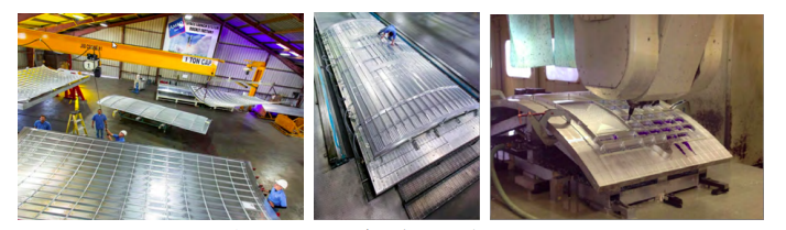
Figure 5 SLS tank panel and level segments
After processing, the wall panel is placed on a special vacuum table for testing, including the geometry, wall thickness, the bottom radius position, the drilling position and the hole diameter, etc. The detection was performed using Verisurf model-based detection software with a laser tracker and a Leica T-type detector (T-Probe). The inspection can automatically generate the parts inspection report, and observe the 3D map of the parts, the machining size and the relative position of the detector, and can detect the hidden points and surfaces difficult to touch by other methods, such as the back of the grid wall. Sboard from processing to packing, to go through more than 20 times of detection, scanning and inspection.
4 Conclusion
The micro-structure evolution law, quality analysis, composition distribution, shape and size, and analyzed. Finally, the high-performance parts with complex structure are formed. The tensile strength reached 448.1MPa, and the elongation rate reached 27.4%. The forming method has low cost, high efficiency and good performance.
Frequently Asked Questions (FAQs)
1. How does precision machining enhance aerospace part performance? Precision machining guarantees components that fit seamlessly within aerospace systems, optimizing efficiency, reliability, and overall performance.
2. Can YICHOU's precision machining handle specialized aerospace materials? Absolutely. Our precision machining proficiency extends to a wide range of aerospace materials, ensuring compatibility with even the most specialized project requirements.
3. What is the typical lead time for precision-machined aerospace components? Lead times vary depending on the complexity and volume of the order. Rest assured, we are committed to delivering promptly without compromising precision.
4. How does YICHOU ensure the precision and quality of each machined part? Quality is at the core of our process. Our components undergo rigorous quality checks throughout production, safeguarding precision and excellence.
5. Does YICHOU offer design consultation for aerospace components? Indeed, we provide design consultation to ensure optimal manufacturability, precision, and efficiency of your aerospace components.
Get Quote
- Visit our website: https://www.nbyichou.com/
- Email us: [email protected]
- Call us/whatsapp: +86 13355741031
- Chat with us: Live chat support available on our website