Meta Description: Avoid cross-port leakage, material fatigue, and internal burrs. A technical guide for design engineers on specifying custom hydraulic manifolds with 5-axis CNC machining. Includes 2026 material data tables and DFM best practices.
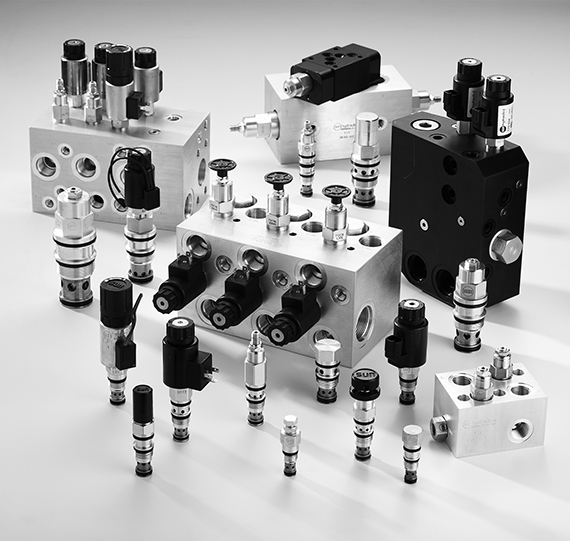
Introduction: The Hidden Cost of a Failed Hydraulic Manifold
In fluid power systems, the humble hydraulic manifold is often overlooked—until it fails catastrophically. A single undetected internal burr, a marginally porous casting, or an incorrectly specified material can trigger:
-
Premature valve jamming
-
Cross-port leakage (internal bypass)
-
Unplanned downtime costing $10,000+ per hour in heavy machinery or offshore operations
For design engineers and procurement managers, selecting the right custom hydraulic manifold machining partner is not just about receiving a block with drilled holes. It is about guaranteeing:
-
Fluid cleanliness (ISO 4406)
-
Structural integrity under cyclic fatigue
-
Dimensional accuracy for cartridge valve cavities (Sun, Rexroth, Parker standards)
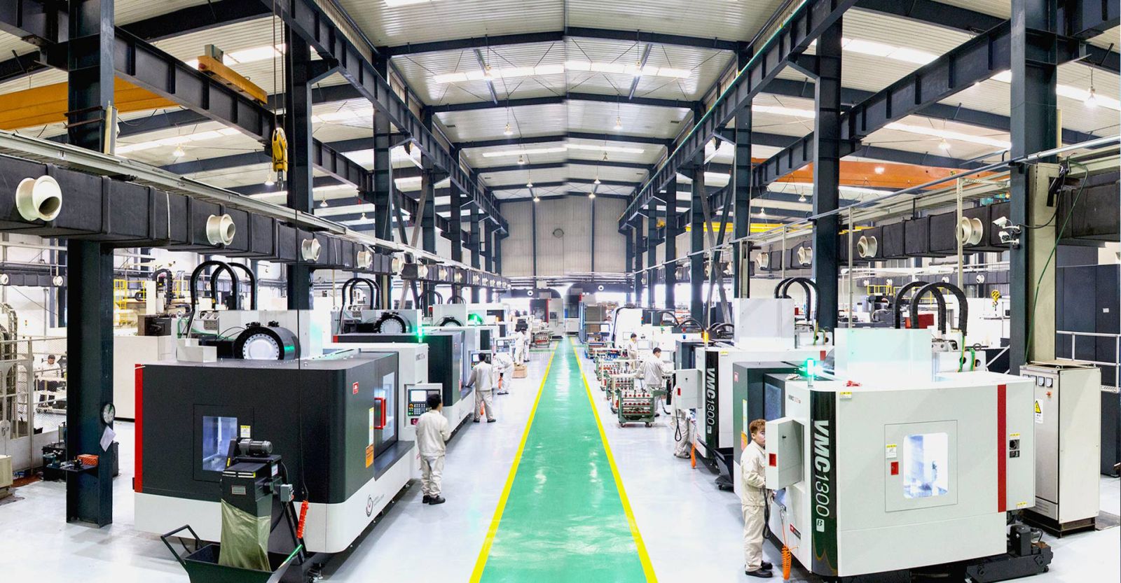
At YICHOU (www.nbyichou.com), we solve these fluid power challenges daily. As an ISO 9001-certified precision CNC machining facility, we combine 5-axis technology with in-house DFM (Design for Manufacturing) analysis to deliver high-pressure hydraulic valve blocks that perform reliably for decades.
This engineering guide walks you through four critical decisions: material selection, 5-axis machining geometry, burr prevention, and custom vs. standard manifold economics.
1. What Is the Best Material for Custom Hydraulic Manifolds?
The best material for hydraulic manifolds depends on operating pressure. High-strength Aluminum (6061-T6) is ideal for applications up to 3,000 psi requiring lightweight properties. For heavy-duty, high-pressure systems up to 5,000 psi or severe-duty environments, Ductile Iron (Durabar 65-45-12) or Stainless Steel (316L) is required to prevent fatigue.
Aluminum 6061-T6 vs. Ductile Iron (Durabar): A Technical Comparison
Aluminum 6061-T6 dominates mobile hydraulics (agricultural equipment, forklifts, aerial work platforms) because it reduces overall system weight. Its natural corrosion resistance also eliminates the need for post-machining plating in dry environments.
However, aluminum has two limitations:
-
Lower fatigue strength under pressure cycling
-
Galling risk when steel fittings are repeatedly threaded
Ductile Iron (Durabar 65-45-12) is the workhorse of industrial hydraulics. Its nodular graphite structure provides:
-
Damping capacity (absorb vibration better than steel)
-
Excellent wear resistance for valve spool interfaces
-
Pressure rating up to 5,000 psi without permanent deformation
When to Specify Stainless Steel (316L) or Titanium for Extreme Environments (Subsea & Offshore)
For subsea blowout preventers (BOPs), offshore platform HPUs, or desalination plants, 316L stainless steel is mandatory. Its molybdenum content resists pitting corrosion from chlorides. However, machining 316L is challenging: it work-hardens rapidly, requiring rigid tooling and low surface speeds.
Titanium (Grade 5 / Ti-6Al-4V) appears only in aerospace or deep-sea applications where weight and corrosion resistance both reach extremes. It costs 5–8× more than 316L but offers unmatched strength-to-weight ratios.
Material Properties Quick Reference for Hydraulic Designers
| Material Grade | Max Pressure Rating (psi) | Weight Density (g/cm³) | Machinability Index (1-100) | Best Application Industry |
|---|---|---|---|---|
| Aluminum 6061-T6 | 3,000 | 2.70 | 90 | Mobile / Agricultural |
| Ductile Iron (65-45-12) | 5,000 | 7.15 | 70 | Industrial / Heavy Equipment |
| Steel (AISI 1045) | 5,000 | 7.85 | 65 | General hydraulic blocks |
| Stainless 316L | 6,000 | 7.98 | 45 | Marine / Subsea / Offshore |
| Titanium Gr5 | 10,000+ | 4.43 | 20 | Aerospace / Deep subsea |
Key takeaway: Higher pressure rating does not always mean “better.” Consider weight, machinability, and operating environment together. For most industrial applications between 3,000–5,000 psi, ductile iron offers the best balance.
2. How Does 5-Axis CNC Machining Prevent Cross-Port Leakage in Hydraulic Valve Blocks?
5‑axis CNC machining eliminates cross‑port leakage by enabling complex, multi‑angle internal cross‑drilling in a single setup. This precision reduces the need for external construction plugs, minimizes cumulative tolerance errors, and ensures perfect concentricity and alignment of intersecting fluid galleries under high hydraulic pressure.
Eliminating Construction Plugs via Complex Internal Flow Paths
Traditional 3‑axis machining forces designers to compromise. To create intersecting fluid channels, machinists must drill from multiple external faces, then seal the unused access holes with threaded plugs. Every plug is a potential leak path.
With simultaneous 5‑axis machining, cutting tools approach the workpiece from any angle. This capability allows:
-
Angled drilling directly between ports without surface access holes
-
Curved fluid galleries that follow the shortest flow path
-
Elimination of 30–50% of construction plugs compared to 3‑axis designs
The result: fewer leak points, cleaner external surfaces, and higher reliability in high-cycle applications.
Achieving Strict Tolerances (±0.005 mm) for Cartridge Valve Cavities (Sun, Rexroth, Parker Cavity Standards)
Cartridge valve cavities (e.g., Sun T‑11A, T‑18A or Rexroth LC series) require extremely tight tolerances:
-
Bore diameter: H7 or H8 tolerance
-
Concentricity: ≤ 0.01 mm
-
Surface finish: Ra ≤ 0.8 µm for seal lands
5‑axis machining directly holds these tolerances because the workpiece is not re‑fixtured. Every cavity is machined relative to the same datum structure. At YICHOU, we combine 5‑axis machining with in‑process probing to verify each cavity before the manifold leaves the machine.
The Importance of In‑House DFM (Design for Manufacturing) Analysis for Reducing “Buy‑to‑Fly” Material Ratios
For complex manifolds, raw material costs often exceed machining costs. A poorly designed manifold can have a buy‑to‑fly ratio (raw material weight ÷ finished part weight) of 5:1 or worse – meaning 80% of the material ends up as chips.
In‑house DFM analysis reduces this ratio through:
-
Wall thickness optimization (avoiding unnecessarily thick sections)
-
Strategic placement of intersecting galleries to minimize deep drilling
-
Combining two separate manifolds into one monolithic block
We provide DFM feedback within 24–48 hours of receiving your STEP or SolidWorks file, often reducing material waste by 30–40%.
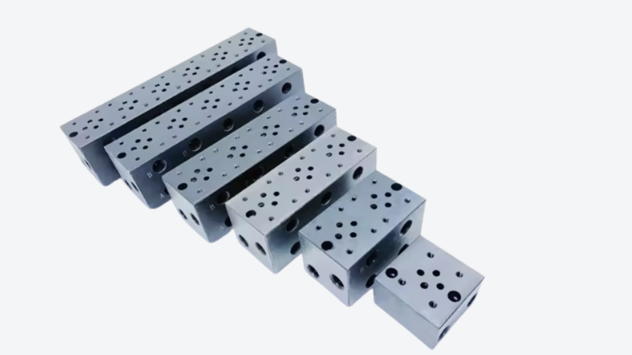
3. Overcoming Internal Burrs: The Hidden Threat to Fluid Power Reliability
Internal burrs at intersecting hydraulic fluid channels cause premature seal degradation and valve jams. Advanced manufacturing eliminates this through high‑speed thermal deburring (TEM) or precise chemical/mechanical brushing, followed by ultrasonic cleaning to guarantee a strict ISO 4406 fluid cleanliness level before shipment.
How Intersecting Drill Holes Create Dangerous Micro‑Burrs
When a drill exits a hole at an intersection, the cutting edge pushes material forward, forming a sharp, folded burr inside the fluid passage. Under hydraulic pressure, these micro‑burrs can break free and circulate, damaging:
-
Spool valve lands (creating leakage paths)
-
Cartridge valve poppets (causing incomplete sealing)
-
Proportional valve orifices (altering flow control accuracy)
Many manifold suppliers ship “deburred” parts that still contain these internal burrs because their process only reaches external edges.
YICHOU’s Post‑Machining Inspection: Borescope Verification and Ultrasonic Cavity Flushing
We implement a three‑stage burr removal protocol:
-
High‑pressure water jet through every gallery immediately after machining
-
Automated brushing using specially shaped nylon brushes with abrasive grit
-
Ultrasonic cleaning in a heated, filtered detergent solution (removing particles down to 5 µm)
After cleaning, we perform 100% borescope inspection of all intersecting galleries. High‑resolution articulating borescopes (2.8 mm diameter) allow us to visually verify that every burr has been removed.
Finally, each manifold is flushed with ISO 4406 Class 15/12/9 fluid, simulating real operating conditions while measuring particle counts.
Protecting Hydraulic Cartridge Valves from Contamination Jams
Most cartridge valve failures trace directly to contamination lodged in the spool or poppet guide. By delivering a burr‑free, ultrasonically clean manifold, you effectively extend valve life by 3–5× compared to using standard commercial manifolds without advanced deburring.
4. Custom vs. Standard Hydraulic Manifolds: Which Is Right for Your Project?
Standard hydraulic manifolds (like D03 or D05 parallel circuit blocks) are cost‑effective for simple, off‑the‑shelf machinery. However, custom‑machined manifolds are essential when space constraints require a compact footprint, integrated valve functions are needed to eliminate plumbing, or custom flow rates are demanded.
Space Optimization: Reducing Hose Connections and Leak Points
A standard D03 aluminum manifold might serve a single valve. For a system with four valves, you would need:
-
Four standard manifolds
-
Eight adapter fittings
-
Twelve hoses (and 24 additional potential leak points)
A custom manifold integrates all four valve mounting surfaces onto one block, with internal drilling replacing every external hose. The result:
-
60–80% fewer fittings and hoses
-
Compact assembly footprint
-
Dramatically lower leak risk
Cost‑Benefit Analysis: Small‑Batch Custom Production Runs for Mid‑Market Equipment OEMs
Myth: Custom manifolds are only economical above 500 pieces.
Reality: With modern CNC workcells, custom manifolds become cost‑competitive at 25–50 pieces.
| Order Quantity | Standard Manifolds (off‑the‑shelf) | Custom Manifold (machined) |
|---|---|---|
| 10 pcs | Lower unit cost, but high assembly labor, many leak points | Slightly higher unit cost, but “plug and play” assembly |
| 50 pcs | Labor cost dominates | Usually lower total system cost |
| 200+ pcs | Not recommended due to reliability issues | Strongly preferred |
For prototypes and low‑volume production (10–50 pieces), YICHOU offers rapid custom machining with typical lead times of 15–20 working days.
Prototype to Mass Production Lifecycle Support
We support your entire product lifecycle:
-
Prototype (1–5 pcs): Machined using the same 5‑axis program and tools as production, guaranteeing functional equivalence.
-
Low‑volume (10–100 pcs/year): Economical production on flexible machining cells.
-
Mass production (500+ pcs/year): Dedicated workholding, optimized toolpaths, and statistical process control (SPC) to maintain tolerances.
5. High‑Conversion FAQ Segment (Targeting Long‑Tail Featured Snippets)
Q1: What surface treatments do you recommend for offshore/marine hydraulic manifolds?
A: For aluminum manifolds in marine environments, hard‑coat anodizing (MIL‑A‑8625 Type III) is essential. It provides 50–70 µm thick aluminum oxide layer with 50–60 Rockwell C hardness, resisting salt spray corrosion.
For carbon steel or ductile iron, we recommend zinc‑nickel plating (5–8% nickel) offering 5–10× better salt spray resistance than standard zinc plating. Manganese phosphating is an alternative for oil‑retentive surfaces but provides lower corrosion protection.
Q2: Can YICHOU machine custom valve blocks directly from our STEP or SolidWorks files?
A: Yes. Our engineering team directly imports .STEP, .IGES, and SolidWorks (.sldprt) files into our CAM system. Within 24–48 hours, we provide:
-
A DFM feedback report (wall thickness, drill depth, intersection angles)
-
Preliminary process routing
-
Quotation for machining, any required surface treatment, and pressure testing
No translation or remodeling is required – we work directly from your native CAD data.
Q3: How do you pressure test custom‑machined hydraulic blocks before delivery?
A: Every YICHOU manifold undergoes 100% hydrostatic pressure testing at 1.5 × maximum working pressure (MWP) for a minimum of 5 minutes. The test setup:
-
Plugs are installed in all ports
-
The manifold is pressurized with inhibited water or low‑viscosity oil
-
No pressure drop, visible leakage, or permanent deformation is permitted
For subsea or safety‑critical applications, we also perform helium leak testing to detect porosity leaks smaller than 1×10⁻⁴ mbar·L/s.
Q4: What is the typical lead time for a custom hydraulic manifold?
A: For a typical custom manifold (size ≤ 300 mm cube, ≤ 20 ports), our standard lead time is 15–20 working days from approval of final drawing and material receipt. Larger or highly complex manifolds (e.g., 500+ kg ductile iron with 50+ ports) require 25–30 working days.
Rush services (8–12 working days) are available for prototype quantities.
Q5: What documentation is provided with each manifold shipment?
A: Every shipment includes:
-
Material test reports (MTRs) traceable to the original mill
-
Dimensional inspection report (including cavity concentricity and thread gauging)
-
Hydrostatic test certificate
-
Cleaning and cleanliness verification report (ISO 4406 class, if specified)
-
Surface treatment certificate (if applicable)
For ISO 9001 or AS9100 customers, we also provide full FAIR (First Article Inspection Report) per AS9102.
Conclusion & Call to Action (CTA)
The YICHOU Advantage
You no longer need to coordinate three different vendors (one for casting/stock, one for machining, one for cleaning/testing) and hope the end result works. At YICHOU, we provide one‑stop custom hydraulic manifold manufacturing:
-
Material sourcing with traceable MTRs (aluminum, ductile iron, steel, stainless, titanium)
-
5‑axis CNC precision machining holding H7 bores and ±0.005 mm tolerances
-
Aggressive deburring with borescope verification and ultrasonic cleaning
-
100% hydrostatic testing at 1.5× MWP
-
Surface finishing (anodizing, plating, phosphating) as required
We serve industrial equipment OEMs, marine hydraulics, mobile machinery, and subsea technology companies worldwide.
Ready to Move from Schematic to Reliable Hardware?
Have a complex hydraulic schematic or a STEP file ready for review?
Get Quote
- Visit our website: https://www.nbyichou.com/
- Email us: [email protected]
- Call us/whatsapp: +86 13355741031
- Chat with us: Live chat support available on our website