In mechanical engineering, the shaft is often the backbone of the entire assembly. Whether transmitting torque in automotive powertrains, maintaining precise motion control in robotics, or enduring heavy loads in industrial pumps, a shaft's performance dictates the reliability of the whole system. A deviation of just 0.01mm in a bearing journal can reduce bearing life by 50%, while excessive runout can destroy a hydraulic seal in hours.
However, custom shaft machining involves far more than just turning a metal bar on a lathe. Factors like runout, heat-treatment warping, and tight tolerances require deep manufacturing expertise. For procurement teams and engineers alike, understanding what separates a reliable shaft manufacturer from an unreliable one is critical to project success.
As a specialized CNC shaft manufacturer, we have compiled this comprehensive guide to help you optimize custom shaft designs for better performance, faster lead times, and reduced costs. Whether you are sourcing for aerospace, automotive, medical devices, or industrial equipment, this guide addresses the engineering challenges and procurement decisions that determine project outcomes.
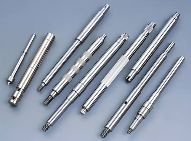
Part 1: Key Engineering Factors in Custom Shaft Machining
1.1 Material Selection: Balancing Strength, Machinability, and Cost
Choosing the right material is the first critical decision in custom shaft manufacturing. The material must withstand operational loads, environmental conditions, and manufacturing processes without compromising final quality.
Carbon Steel Shafts
Carbon steel offers excellent machinability and is relatively affordable, making it suitable for general-purpose mechanical shafts. Grade 1045 is widely used for moderate-load applications like pump shafts and motor shafts. It responds well to heat treatment when higher hardness is needed.
Alloy Steel Shafts
Alloy steels like 4140, 8620, and 4340 are the standard for heavy-duty drive shafts. They respond exceptionally well to heat treatments like carburizing and induction hardening. 4140 pre-hardened steel in the 28–32 HRC range machines predictably and resists deflection better than softer mild steel of the same diameter. For applications requiring higher fatigue resistance, 42CrMo4 and 31CrMoV9 are excellent choices.
Stainless Steel Shafts
Grades 304, 316, and 17-4PH are excellent for corrosive environments or medical applications. 17-4PH in the H1025 condition offers similar stiffness to alloy steels with the added benefit of corrosion resistance, making it ideal for non-magnetic or corrosion-resistant requirements.
Aluminum and Titanium Shafts
Aluminum alloys are lightweight and corrosion-resistant, ideal for weight-sensitive applications such as aerospace components. Titanium offers an exceptional strength-to-weight ratio for high-performance applications.
Nickel Alloys
Inconel and other nickel alloys provide excellent high-temperature strength and corrosion resistance for extremely demanding applications such as chemical plants and turbines.
1.2 Mastering Tolerances and GD&T
Shafts frequently interface with bearings, gears, and couplings, making Geometric Dimensioning and Tolerancing (GD&T) crucial. Understanding the ISO system of limits and fits is essential for interpreting engineering drawings correctly.
Diameter Tolerances
Common ISO shaft tolerances include:
| Tolerance Class | Fit Type | Typical Application |
|---|---|---|
| h6 / h7 | Clearance/Transition Fit | Standard precision shafts, coupling interfaces |
| g6 / f7 | Sliding/Running Fit | Hydraulic valve spools, linear motion guide rods |
| k6 / m6 | Interference/Press Fit | Bearing seats, gear seats requiring no relative motion |
H6 fits are used when a tight and controlled fit is required, while g6 fits provide slight clearance for easier assembly. Correct tolerance ensures smooth rotation and proper load transfer.
Critical GD&T Features for Shafts
| GD&T Feature | Why It Matters | Typical Target |
|---|---|---|
| Total Runout | Prevents vibration and premature bearing failure at high speeds | < 0.01mm |
| Concentricity / Coaxiality | Ensures gear seats and bearing seats share the same center axis | Verified via CMM |
| Cylindricity | Controls roundness, straightness, and taper along the entire shaft length | Critical for press-fit components |
| Straightness | Prevents bowing from internal stresses or machining pressure | Essential for long, slender shafts |
In high-speed electric motors or hydraulic pumps, excessive Total Indicated Runout (TIR) often manifests as audible noise, seal leakage, or unexplained bearing failures. For a shaft with a nominal dimension range between 50 mm and 80 mm, using ISO 286 Grade IT6, the tolerance zone is just 19 µm.
Surface Finish Requirements
Surface finish directly affects bearing life and stability. A rough surface breaks lubrication and increases wear. Typical bearing surfaces require Ra 0.4 to 1.6 µm. Rough finishes increase heat and friction during operation and can damage rolling elements over time.
Part 2: Core Manufacturing Processes for Custom Shafts
To achieve tight tolerances, custom shafts often undergo multi-step manufacturing workflows. The process selection directly affects price and delivery time.
2.1 CNC Turning and Swiss Machining
For standard stepped shafts, CNC turning delivers high efficiency. For micro-shafts or high-aspect-ratio shafts, Swiss CNC machining prevents part deflection by supporting the workpiece close to the cutting zone.
2.2 Turn-Mill Multi-Tasking
Modern multi-axis CNC machines allow manufacturers to turn the main diameter and mill keyways, splines, flats, or cross-holes in a single setup, eliminating positioning errors. This approach is essential for keyed shafts, threaded shafts, and splined shafts that require multiple features aligned with high precision.
2.3 Precision Grinding
For bearing seats and seal journals, turning alone may not achieve the required finish. Cylindrical or centerless grinding brings surface roughness down to Ra 0.2–0.4 µm. Grinding is also ideal for one-sided dimensional control, achieving tolerances of ±0.005 mm or better on critical features.
Why Grinding Is Required After Turning:
Turning leaves small errors due to tool deflection and cutting forces. Grinding corrects these errors and brings the shaft to final specification:
-
Achieves tighter tolerances than turning alone
-
Improves roundness and straightness
-
Removes distortion after heat treatment
-
Produces a consistent surface finish
Cylindrical vs. Centerless Grinding:
Cylindrical grinding is used when alignment and accuracy are critical, handling complex shaft features better. Centerless grinding is suited for high-volume production, allowing continuous and faster processing.
Part 3: Overcoming Common Shaft Machining Challenges
3.1 Preventing Shaft Deflection
Long, slender shafts tend to bend under tool pressure. Three primary causes contribute to deflection: cutting force pushing the workpiece, gravity pulling it, and heat causing axial expansion.
Design-Stage Solutions:
-
Optimize the Length-to-Diameter (L/D) Ratio: An L/D ratio above 8:1 starts to be difficult; above 12:1 is challenging; above 20:1 requires active support during cutting. If the assembly layout allows, use a stepped shaft or slightly larger diameter over the critical length.
-
Choose a Stiffer Material: Material properties that matter most for long shafts are the modulus of elasticity (resistance to elastic bending) and pre-hardened condition (uniform hardness, no internal stress gradients).
-
Design Stepped Shafts with Fillets: A stepped shaft—thicker where the bending moment is largest—is far easier to machine straight than a uniform-diameter stick. Transitions should have generous fillet radii (typically 1–2 mm minimum) to spread stress.
Manufacturing-Stage Solutions:
-
Follower Rests and Steady Rests: These provide physical support to the middle of the shaft during cutting, effectively turning a long, springy part back into something that behaves like a short, rigid part. Steady rests are deployed as soon as the L/D ratio passes roughly 6:1.
-
Reverse Turning / Pull Turning: Conventional turning compresses the workpiece. Reverse turning reverses the feed direction so the tool pulls away from the chuck, putting the workpiece into tension. Tension-stiffened shafts are dramatically less prone to deflection.
-
High-Pressure Coolant: Coolant at 70–150 bar evacuates chips from the cut and carries heat away fast enough that thermal growth stays within controllable limits.
Advanced Methods:
Recent research has demonstrated that parallel multidirectional cutting (PMC)—using two tools to simultaneously cut the workpiece in forward or reverse directions—significantly improves machining precision and efficiency for slender shafts, with promising applications in high-precision manufacturing industries such as aerospace and medical devices.
3.2 Managing Thermal Expansion and Residual Stress
Heat generated during machining or subsequent heat treatments can distort shaft straightness. The reliable sequence for precision shafts is:
-
Rough turn to within 1–2 mm of final diameter, removing the bulk of stock and residual stress
-
Stress relieve in a controlled furnace cycle (typically 550–650 °C for steel) to let the part settle into a stable stress state
-
Semi-finish to within 0.2–0.5 mm of final dimension
-
Finish turn to final tolerance with light passes, low radial engagement, and sharp tools
The intermediate stress-relieving step is what many shops skip—and it is often the difference between a shaft that runs true and one that requires rework.
Thermo-Mechanical Treatment:
Research indicates that during martensitic transformation, steel loses tensile strength and undergoes slight deformation (σ₀₂ is reduced by 12 to 14 times). At quenching temperatures, the residual stress field is reduced to zero and is uniform across the cross-section. However, maintaining this state during cooling is technologically difficult, requiring careful preparation and loading conditions.
3.3 Solving Keyway Fatigue Failures
A standard keyway has sharp 90° corners at the bottom of the slot. Under cyclic torsional loads, the stress at these corners is 3.5–4.0 times higher than the nominal stress in the shaft body—the stress concentration factor (Kt).
The proven solution: Add a radius at the internal corners. A sharp corner has a theoretical Kt approaching infinity. A 0.030" radius drops the Kt to approximately 1.8—less than half the stress concentration. One manufacturer reported extending shaft service life from 8 months to over 2 years simply by adding a 2mm radius where a customer had specified a sharp corner.
Part 4: Common Shaft Types and Their Applications
Understanding the application helps select the right manufacturing approach:
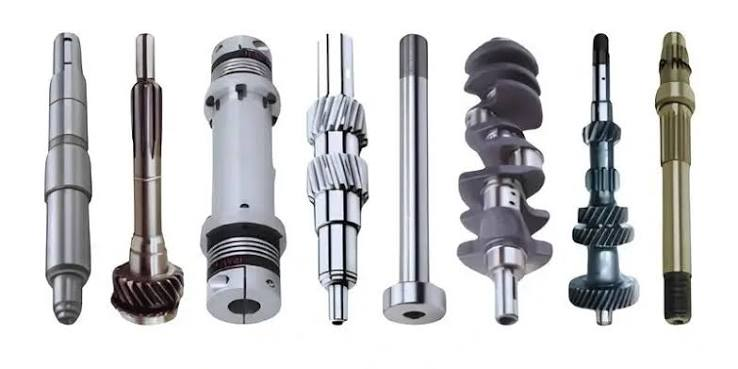
| Shaft Type | Key Features | Typical Applications |
|---|---|---|
| Keyed Shafts | Rectangular keyway for positive torque transmission | Motors, pumps, general machinery |
| Splined Shafts | Longitudinal grooves for high torque with frequent engagement | Hydraulic equipment, automobile gearboxes |
| Threaded Shafts | Internal or external threads for linear motion conversion | Fastening, positioning systems, CNC equipment |
| Tapered Shafts | Gradual diameter change for firm assembly and easy disassembly | Spindle assemblies, power output ends |
| Gear Shafts | Integrated gear teeth or multiple gear mounting positions | Gearboxes, large mechanical equipment |
| Worm Shafts | Worm-like disks meshing with worm gear for large reduction ratios | Winch systems, lifting platforms, machine tool feed mechanisms |
Part 5: Design for Manufacturability (DFM): How to Lower Shaft Costs
The decisions made during design have a profound effect on product cost—studies suggest that 75 to 90% of project costs are determined during the first 7 to 8% of development time.
5.1 Relax Non-Critical Tolerances
Only specify micron-level tolerances where bearings or seals sit. Standard shaft bodies can operate safely with looser tolerances. Over-tolerancing—applying unnecessarily tight geometric tolerances—can significantly raise manufacturing costs and extend lead times.
5.2 Standardize Tool Relief Radii
Match internal step radii to standard carbide insert nose radii (e.g., 0.4 mm or 0.8 mm) to avoid custom tooling fees. The cost difference between a standard and custom radius can be substantial, particularly for production runs.
5.3 Design Unified Keyways
If your shaft features multiple keyways, design them with the same width so they can be milled using a single tool setup. Each tool change adds setup time and opportunity for error.
5.4 Cost Drivers in Shaft Machining
Shaft machining cost depends on:
-
Material selection (harder materials increase tool wear and machining time)
-
Size and tolerances (tight tolerances require more passes and slower cutting speeds)
-
Production method and volume
-
Finishing requirements
-
Tool selection and setup time
Optimization tips:
-
Standardizing dimensions helps reduce cost and machining steps
-
Use coated carbide tools to extend tool life
-
Monitor tool wear and replace predictively to avoid quality issues
5.5 Real-World Cost Comparison
Based on supplier data from major manufacturing hubs, pricing varies significantly based on complexity, material, and volume:
| Supplier Profile | Product Type | Unit Price Range | Min Order | Best For |
|---|---|---|---|---|
| High-volume precision | Custom Machined Shafts | $0.05–$0.10 | 100–500 pcs | Budget-sensitive bulk orders |
| Mid-volume custom | Pneumatic & Mechanical Shafts | $0.10–$2.00 | 10–100 pcs | Prototypes and mid-volume precision parts |
| Low-volume OEM | Precision Linear Shafts | $0.50–$1.50 | 10 pcs | Automation guides, conveyor rollers |
| Heavy industrial | Large Forged Gear Shafts | $400–$900 | 1 pc | Mining, wind energy, construction equipment |
Lower prices often correlate with higher MOQs and limited customization. Premium pricing reflects access to advanced materials and specialized processes. Buyers should align sourcing strategy with lifecycle cost rather than upfront price—especially when durability and uptime are paramount.
Part 6: Strategic Sourcing—How to Select a Reliable Shaft Manufacturer
Selecting the right manufacturing partner requires more than comparing price lists. A structured assessment ensures alignment between technical capability, quality systems, and operational responsiveness.
6.1 Evaluate Technical Infrastructure
Precision shafts demand specialized tooling. Confirm whether the supplier operates:
-
Multi-axis CNC lathes (4-axis and 5-axis turning centers)
-
Centerless or cylindrical grinding systems
-
Hard-turning machines for hardened steels like 4140 or 17-4PH
For corrosion-resistant variants (e.g., 304/316 stainless), inquire about post-processing options such as sandblasting, passivation, or chrome plating.
Design support should include GD&T-compliant drawings and compatibility with STEP, DWG, or PDF formats. Reverse engineering services add value when legacy parts lack documentation.
6.2 Assess Quality Control Protocols
ISO 9001 certification remains a baseline indicator of process discipline. However, deeper validation involves reviewing:
-
First-article inspection (FAI) reports
-
In-process gauging during production runs
-
Final verification via coordinate measuring machine (CMM)
-
Process capability studies (Cp/Cpk values)
-
Surface finish and concentricity testing protocols
-
Material traceability (mill test reports per EN 10204 3.1)
For regulated sectors—including medical devices or EU machinery—RoHS or CE compliance may be mandatory.
6.3 Evaluate Responsiveness and Scalability
Key operational metrics to assess:
| Metric | What It Indicates | Target |
|---|---|---|
| On-Time Delivery Rate | Reliable scheduling and logistics | ≥ 95% |
| Reorder Rate | Customer satisfaction and product consistency | ≥ 25% |
| Response Time | Technical clarification and issue resolution speed | < 3 hours |
| Production Scope | OEM-focused vs. general trading | In-house CNC machining capability |
Suppliers with high reorder rates—such as Dongguan Best Precision (32%) and Sichuan Dawn Precision (27%)—suggest dependable output quality and customer retention.
6.4 Verification Strategies for Buyers
To mitigate procurement risk:
-
Request sample batches before committing to large volumes
-
Ask for dimensional reports or video inspections of critical processes
-
Verify whether the supplier operates their own facility (avoid intermediaries)
-
Conduct virtual audits via video walkthroughs of CNC lines and QC checkpoints
-
Request documented evidence of material traceability and inspection reports
Part 7: Quality Assurance—Ensuring Zero-Defect Shafts
A reliable shaft manufacturer doesn't just cut metal; they verify every dimension. Quality control isn't just a final step—it's built into every stage of the manufacturing process.
7.1 Modern Inspection Technologies
Coordinate Measuring Machines (CMM)
The gold standard for dimensional metrology provides traceable, high-accuracy measurements with sub-micron uncertainty. However, for complex shafts with over 200 distinct geometric characteristics, CMM inspection can be prohibitively slow.
Optical Measurement Systems
Advanced vision-based measurement methods can output dimensions of various features such as diameter, segment length, and chamfer simultaneously. Recent innovations have doubled measurement accuracy compared to traditional methods.
Dynamic Balancing
Essential for high-RPM shafts to eliminate destructive vibrations before installation. A shaft can pass all dimensional inspections but still fail in service if it is out of balance.
7.2 Quality Benchmarks
-
On manual equipment, experienced machinists can consistently hold ±0.025mm tolerances, while CNC can achieve ±0.01mm for critical features
-
For high-speed applications, surface roughness of Ra 0.2–0.4 µm on bearing journals is typically required
-
A 0.0005" (±0.013mm) bearing journal diameter tolerance with a 16 Ra finish is standard for demanding applications
7.3 Parameters That Control Shaft Quality
The most important parameter checks for CNC turned shaft concentricity include:
| Parameter | Why It Matters | How to Verify |
|---|---|---|
| Runout | Affects tolerance stability and inspection confidence | Confirm material, datum, critical dimensions, and first article inspection |
| Concentricity | Ensures uniform central axis across multiple shaft steps | CMM measurement |
| Workholding | Affects tolerance stability and machining sequence | Verify fixture plan and finishing allowance |
| Center Support | Critical for preventing deflection | Check steady rest deployment |
| Surface Finish | Directly affects bearing life and lubrication | Surface roughness testing |
Part 8: Conclusion and Call to Action
Machining custom shafts requires a balance of advanced machinery, strict quality control, and deep material knowledge. Whether you need prototype shafts or high-volume production runs, working with an experienced CNC machining partner ensures your components perform reliably under real-world conditions.
Key Takeaways for Engineers and Procurement Teams:
-
Material selection must balance strength, machinability, and cost—alloy steels for heavy-duty applications, stainless steel for corrosion resistance, and aluminum for weight-sensitive designs.
-
Tolerances and GD&T must be specified realistically—only tighten tolerances on critical features to control costs.
-
Deflection control requires design optimization (L/D ratio, stepped shafts) and manufacturing techniques (steady rests, reverse turning, high-pressure coolant).
-
Thermal management demands proper stress-relieving cycles between rough and finish machining.
-
Cost optimization comes from standardizing radii, unified keyways, and relaxing non-critical tolerances.
-
Supplier selection should evaluate technical infrastructure, quality protocols, on-time delivery, and reorder rates—not just price.
-
Quality assurance requires CMM inspection, optical measurement, and dynamic balancing for high-speed applications.
Before placing your next order, ask your supplier:
-
What is your experience with my specific material and shaft geometry?
-
Can you provide a DFM review to identify cost-saving improvements?
-
What quality inspection equipment do you operate (CMM, optical measurement, dynamic balancing)?
-
What is your thermal management and stress-relieving process for heat-treated shafts?
-
Can you share on-time delivery rates and reorder rates from existing customers?
Need high-precision shafts for your next project?
Send us your 3D CAD files and drawings today for a fast quote and a complimentary DFM analysis from our engineering team. Let's make your next shaft project a success—from design to delivery.
Keywords: Custom Shaft Machining, CNC Shaft Machining, Precision Shaft Manufacturing, CNC Turning Shafts, Shaft Machining Tolerances, OEM Shaft Manufacturer, Shaft Deflection Prevention, Shaft Material Selection, CNC Shaft Sourcing Guide
Get Quote
- Visit our website: https://www.nbyichou.com/
- Email us: [email protected]
- Call us/whatsapp: +86 13355741031