*Everything you need to know about IGV, OGV, and NGV – From Material Selection to Advanced 5-Axis Machining*
1. Introduction: The Silent Architects of Energy Conversion
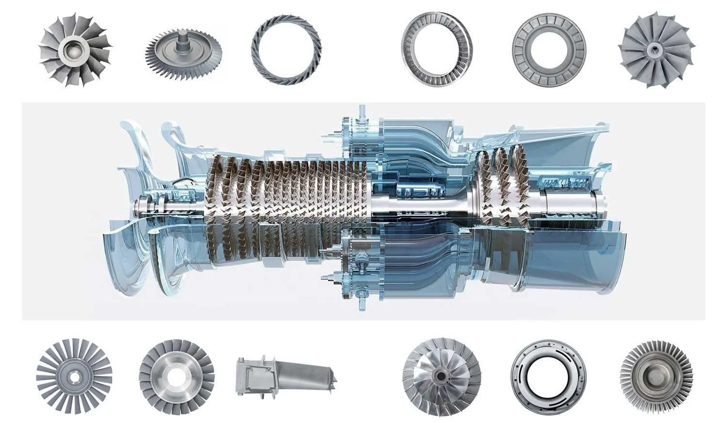
In the complex world of turbomachinery—from the gas turbines powering a Boeing 777 to the centrifugal compressors driving chemical plants—there is one component that dictates efficiency, stability, and longevity: the Guide Vane.
Despite their static appearance, guide vanes are the "traffic controllers" of fluid dynamics. They convert chaotic, high-velocity flow into vectored, usable energy. For engineers and procurement managers, the difference between a high-performance rotor and a catastrophic failure often lies in the geometry and metallurgy of these stationary blades.
The industry pain point is universal: Efficiency loss due to aerodynamic stall, thermal fatigue cracking in nozzle rings, and unplanned downtime caused by erosion. As energy prices fluctuate and emission regulations tighten (IEA 2025 benchmarks), optimizing the stator side of your machine is no longer optional.
In this 10,000-word technical deep dive, we will dissect the classification of Inlet Guide Vanes (IGV), Outlet Guide Vanes (OGV), and Nozzle Guide Vanes (NGV). We will explore material science (from 17-4PH to Inconel 718), review 5-axis CNC manufacturing versus investment casting, and provide actionable data for your next service overhaul.
2. Fundamental Principles & Classification
2.1 The Aerodynamics of the Stator
Unlike rotating blades that add energy, guide vanes optimize it. According to the Euler turbomachine equation, the torque is proportional to the change in angular momentum. Guide vanes adjust the velocity vector (absolute velocity VV and angle αα) entering or exiting the rotor.
By imparting a pre-swirl (IGV) or removing the tangential velocity component (OGV), these vanes ensure the rotor operates at its optimal incidence angle, preventing the destructive phenomenon of flow separation.
2.2 Core Classification Detailed
Inlet Guide Vanes (IGV)
Located at the intake of compressors, IGVs are often fitted with Variable Geometry (VG) actuators. By rotating the vane profile around a trunnion, the mass flow rate can be throttled without losing pressure ratio. In centrifugal compressors, closing the IGV reduces power consumption by up to 9% compared to discharge throttling.
Outlet Guide Vanes (OGV)
Post-rotor, the fluid has high residual swirl (tangential velocity). OGVs act as diffusers, converting this kinetic energy into static pressure rise. The primary challenge here is reducing "exit loss." An aerodynamically poor OGV can destroy the efficiency gains made upstream.
Nozzle Guide Vanes (NGV)
In the turbine section, NGVs face the harshest environment. They take hot, high-pressure gas (from the combustor) and accelerate it to supersonic speeds (M>1.0M>1.0) before it hits the turbine blades. Here, thermodynamics rule: h1+V122=h2+V222h1+2V12=h2+2V22. The NGV converts enthalpy into kinetic energy.
2.3 Fixed vs. Adjustable
-
Fixed Vanes: Cost-effective for steady-load operations (e.g., steam turbines in base-load power plants).
-
Adjustable (Variable) Vanes: Essential for wide operational turndown ratios (e.g., turbochargers in diesel engines or gas turbines for grid balancing).
3. Engineering Challenges & Client Pain Points
For a facility manager, a broken guide vane is a fiscal crisis. Let’s quantify the risks.
3.1 Aerodynamic Stall & Surge
The "stall margin" is the buffer between operating pressure and the surge line. If IGVs close too rapidly or the profile is incorrect, boundary layer separation occurs on the vane's suction side. This causes rotating stall, leading to a full-system surge—a violent reversal of flow that can destroy thrust bearings and crack casings in milliseconds.
3.2 Thermal Fatigue in NGVs
In a 60Hz industrial gas turbine, an NGV experiences 3,600 thermal cycles per minute. The leading edge is subjected to 1100∘C1100∘C gas, while the blade root (fir-tree attachment) is cooled to 400∘C400∘C via bleed air. This thermal gradient induces creep (time-dependent plastic deformation). A 2% creep elongation changes the vane throat area, derating the turbine’s power output by 5-7%.
3.3 Erosion, Corrosion, and Wear
-
Solid Particle Erosion: Inlet air filtration failure allows silica dust to impact the leading edge at high velocity, eroding the profile like sandblasting.
-
Fretting Corrosion: At the vane-root interface, micro-vibrations wear away the protective oxide layer, leading to crack initiation (CFD-correlated failures).
-
Cold Weather Risks: For IGV in arctic LNG plants, ice accretion on the vane surface changes the aerodynamic shape, often causing mechanical lock-up of the variable vanes.
3.4 The Financial Impact
The 4-D Equation of Failure:
-
Downtime: A 50,000 guide vane set failing can cause \2M/day in lost LNG production.
-
Disassembly: Unplanned NGV replacement requires pulling the entire upper casing—a 2-week crane operation.
-
Chain Reaction: A fractured NGV piece passing through the turbine will wipe out the entire blade row.
4. Advanced Material Science in Vane Manufacturing
Selecting the wrong alloy is a death sentence for your vane. Here is the engineering breakdown for 2025 standards.
4.1 Stainless Steel Series (The Standard)
-
400 Series (410/403): Martensitic stainless. Excellent for steam turbine IGVs up to 550°C. Good resistance to water droplet erosion.
-
17-4PH (Precipitation Hardening): The workhorse of centrifugal compressors. High strength (UTS up to 1310 MPa) with decent corrosion resistance. Limitation: Loses hardness above 315°C due to overaging.
4.2 Superalloys (The High-Temperature Guardians)
-
Inconel 718: Gamma prime (γ′γ′) strengthened. Retains yield strength up to 700°C. Preferred for aircraft engine OGVs and industrial gas turbine (IGT) stages 1-3. Lead time: Requires vacuum induction melting (VIM).
-
Mar-M247: High-tungsten, high-tantalum alloy used for cast NGVs. Excellent creep rupture strength up to 980°C. Requires complex solution heat treatment cycles.
-
Hastelloy X: Outstanding oxidation resistance; often used for combustor cans and associated NGVs.
4.3 Lightweight Alternatives
-
Titanium Grade 5 (Ti-6Al-4V): High strength-to-weight ratio. Essential for aero-engine IGVs where every gram reduces fuel burn. Caution: Notorious for galling in variable vane bushings.
-
Aluminum 7075-T6: Only for low-temperature, low-stress industrial fan guide vanes (ambient air only).
4.4 Heat Treatment & Certification
The microstructure dictates performance.
-
Solution Treatment: Dissolves secondary phases.
-
Aging/Hardening: Precipitates fine intermetallic phases (like γ′′γ′′ in Inconel 718) that block dislocation movement.
Critical Standard: All components for oil & gas or power gen must meet EN 10204 Type 3.1 certification. This certifies traceability from the melt source to the final machined part.
5. Precision Manufacturing Processes
To achieve the tight tolerances required by modern CFD optimization (±0.01mm±0.01mm profile tolerance), we rely on two primary methods: Investment Casting and 5-Axis CNC Machining.
5.1 Investment Casting (Lost Wax)
Best suited for complex, hollow NGVs with internal cooling passages.
-
Near-Net Shape: Reduces scrap material (Superalloy scrap costs $50/kg+).
-
Directional Solidification (DS): Grains aligned parallel to the principal stress axis (centrifugal force). Reduces thermal fatigue cracking.
-
Single Crystal (SX): Elimination of grain boundaries entirely. The ultimate in creep resistance (used in Rolls-Royce level engines). Trade-off: Extremely high cost and 12+ week lead times.
5.2 5-Axis CNC Machining
For variable IGVs (which require a precise airfoil shape plus actuator arms) and replacement parts for obsolete machinery.
-
Geometric Precision: A DMG MORI 5-axis machine holding a ±0.01mm±0.01mm profile tolerance ensures the "throat area" (critical for mass flow calculation) is exact.
-
Complexity: Allows machining of twisted airfoils where the leading edge has a different angle than the trailing edge.
-
GD&T (Geometric Dimensioning and Tolerancing): Key callouts include:
-
Profile of a surface (Control on airfoil suction/pressure side).
-
Total Runout (For the vane trunnions).
-
5.3 Surface Treatment Technologies
The surface is the first line of defense.
-
Thermal Barrier Coatings (TBC): Yttria-stabilized zirconia (YSZ) applied via APS (Air Plasma Spray). A 0.5mm TBC layer reduces base metal temperature by 200°C.
-
HVOF (High-Velocity Oxygen Fuel): Tungsten carbide coatings. Applied to leading edges of IGVs in sand-prone environments (e.g., Middle East gas compression). Hardness > 1200 HV.
-
Electrolytic Polishing vs. Shot Peening:
-
Electropolish: Reduces surface roughness (Ra 0.2µm) to prevent fouling.
-
Shot Peening: Induces compressive residual stress to prevent crack initiation in the blade root.
-
6. Quality Control & Testing Standards
"We trust, but we verify." In guide vane manufacturing, verification is a destructive and non-destructive ballet.
6.1 Dimensional Inspection
-
CMM (Coordinate Measuring Machine): A Zeiss Contura scans the airfoil profile. We compare the point cloud to the original STEP file (Nominal vs. Actual deviation).
-
Blue Light Scanning: For complex variable vane assemblies, full-field scanning checks the alignment of the unison ring holes with the vane arm bushings.
6.2 Non-Destructive Testing (NDT)
-
Fluorescent Penetrant Inspection (FPI): Mandatory for all safety-critical NGVs. Reveals surface-breaking micro-cracks caused by grinding burns.
-
X-Ray / CT Scanning: For investment cast parts, X-ray reveals core shift (if internal cooling passages are misaligned) or porosity inclusion.
6.3 Performance Validation
-
Moment Weight Balancing: For rotating assemblies, guide vane stages are weight-matched to avoid harmonic vibration.
-
Flow Rig Testing: A statistically random sample is placed in a wind tunnel to verify the CdCd (Discharge Coefficient) matches the aerodynamic design data.
7. Case Studies & Real-World Impact
Case Study A: Centrifugal Air Compressor OGV Redesign
Problem: A chemical plant in Texas reported that their 5 MW centrifugal compressor was consuming 4.8 MW at full load—8% above design efficiency. The OGV set had a 20-year-old design with thick trailing edges.
Solution: We performed reverse engineering (3D scanning) and CFD optimization to reduce trailing edge thickness from 1.2mm to 0.4mm and added a Gurney flap feature.
Result: Power draw dropped to 4.45 MW. 5.8% efficiency gain. ROI achieved in 8 months.
Case Study B: Gas Turbine NGV Life Extension (Mar-M247 vs. IN738)
Problem: A 35MW SGT-800 user experienced NGV cracking every 8,000 hours (18 months), requiring hot gas path inspection.
Solution: Switched from conventionally cast IN738 to Directionally Solidified Mar-M247 with a premium TBC coating.
Result: Time Between Overhaul (TBO) extended to 12,000 hours. 50% increase in service life. Reduced downtime cost by $1.2M over 5 years.
Case Study C: Reverse Engineering for Obsolete Turboexpander
Problem: An LNG plant had a 1980s turboexpander with corroded IGVs. The OEM went bankrupt. No drawings existed.
Solution: Using a 5-axis laser scanner and conjugate heat transfer (CHT) simulation, we recreated the solid model. Machined a set of 20 IGVs in Inconel 625 via Wire EDM + 5-axis finishing.
Result: Turbine back online in 6 weeks. Original performance envelope restored.
8. Sourcing & Supply Chain Management
How do you vet a guide vane manufacturer? Use this checklist in your RFQ.
8.1 The Vendor Audit Checklist
-
Design Capability: Do they have CFD and FEA (Finite Element Analysis) engineers? Can they reverse engineer obsolete parts?
-
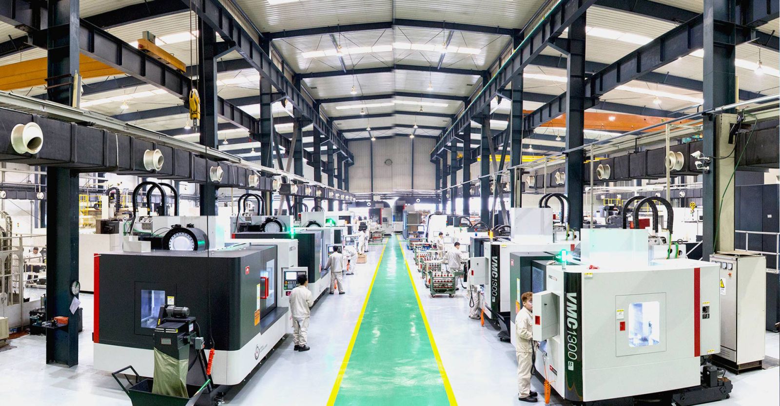
Asset List: Do they own 5-axis machines (not sub-contracting)? Do they have in-house CMM and X-Ray?
-
Certifications: ISO 9001:2015 is baseline. AS9100D (Aerospace) or API 20A is required for oil & gas.
8.2 Critical RFQ Parameters
When you send your RFQ, disclose this data:
-
Drawing: Provide STEP (.stp) or Original PDF. Specify Revision level.
-
Material: Exact UNS designation (e.g., UNS N07718 for Inconel 718).
-
Tolerance: Indicate GD&T datums. Specifically call out airfoil profile tolerance.
-
Operating Temp: Max continuous temp and Min start-up temp.
8.3 Lead Time Management
-
Casting: Requires pattern tooling (2-4 weeks). Casting lead time: 8-12 weeks.
-
Machined from Solid (Billet): No tooling cost. Raw material acquisition (2 weeks). Machining (3-4 weeks).
-
Strategic advice: Keep a "critical spares" stock for your top 3 IGV stages.
9. Future Trends in Guide Vane Technology
Additive Manufacturing (3D Printing)
Laser Powder Bed Fusion (LPBF) allows us to print triply periodic minimal surface (TPMS) cores. This creates internal cooling channels that conventional casting cannot achieve—increasing convective heat transfer by 40% while reducing airflow bleed.
Smart Vanes (Embedded Sensors)
Photonic sensors (Fiber Bragg Gratings) are being printed inside IGVs. These allow the operator to see the real-time strain and temperature at the blade root. This Digital Twin data allows for condition-based maintenance rather than scheduled overhauls.
Eco-Friendly Coatings
Strict EPA and EU ETS regulations are pushing us toward Chrome-free HVOF coatings. The industry is shifting from traditional chrome-carbide to Iron-based amorphous alloys to lower carcinogenic waste during manufacturing.
10. Conclusion & Strategic Advice
Guide vanes are not just "metal plates in a flow stream." They are precision instruments for energy management. A poorly manufactured NGV will cost you in fuel and downtime; a precisely engineered IGV will give you the turndown agility needed for modern grid demands.
Strategic Takeaway:
-
For New Builds: Invest in 5-axis machined, variable IGVs with TBC coatings.
-
For MRO (Maintenance): Upgrade obsolete OGVs with modern, CFD-optimized trailing edges.
-
For Supply Chain: Never accept "general certifications." Demand EN 10204 3.1 for peace of mind.
we combine metallurgical science with German/Japanese-level machining precision. We don’t just sell parts; we engineer performance margins.
Get in Touch with Yichou
Let Yichou help you achieve excellence in your next project. Whether you need raw materials, custom alloy solutions, or precision-manufactured components, our team is ready to assist.
- Email us: [email protected]
- Call us/whatsapp: +86 13355741031
- Chat with us: Live chat support available on our website