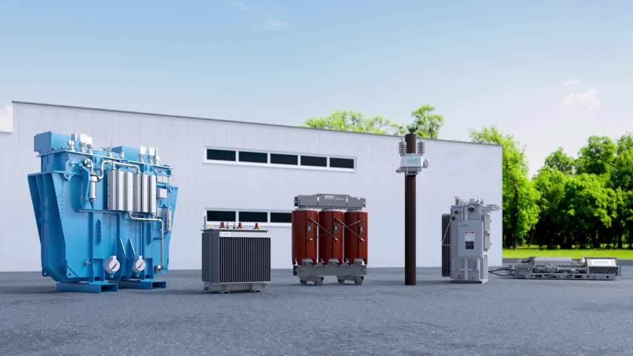
Introduction: The Unsung Heroes of the Electrical Grid
Imagine a sprawling city at night, a vibrant tapestry of light and energy. Now, imagine that energy suddenly vanishing, plunging everything into darkness. What prevents this chaos? The answer lies in a complex, meticulously engineered system, and at its heart are its silent, steadfast guardians: transformers.
While most people have seen a transformer on a utility pole, few understand their critical role. For electrical engineers, procurement managers, and utility specialists, however, selecting the right transformer isn't just a matter of specification—it's a decision that impacts safety, efficiency, cost, and the very reliability of the electrical infrastructure.
This guide is designed to demystify the complex world of transformers. We will dissect the four pivotal types that form the backbone of any power system: the mighty Power Transformers, the ubiquitous Distribution Transformers, and the precision instruments known as Current Transformers (CT) and Voltage Transformers (VT/PT). By the end, you will not only understand their distinct functions but also be equipped to make informed decisions for your next project.
Part 1: The Workhorses: Power Transformers vs. Distribution Transformers
At the most fundamental level, all transformers operate on the principle of electromagnetic induction to change the voltage level of an alternating current (AC). However, their application, design, and placement create a clear division of labor, starting with the two that handle bulk power: Power and Distribution Transformers.
1.1 Power Transformers: The Long-Distance Haulers
What They Are and What They Do:
A Power Transformer is the heavyweight champion of the electrical grid. Its primary mission is to enable efficient, long-distance transmission of electrical energy. When electricity is generated at a plant, it is typically produced at a medium voltage level (e.g., 11-33 kV). Transmitting this power over hundreds of miles at this voltage would result in catastrophic energy losses due to the square of the current (I²R losses).
This is where the Power Transformer comes in. Located directly at the generating station, it "steps up" the voltage to extremely high levels—typically 138 kV, 230 kV, 500 kV, or even higher. According to the power equation (P = VI), for a constant power, increasing the voltage drastically reduces the current. A lower current means significantly reduced resistive losses in the transmission lines, making cross-country power transmission feasible and economical.
Key Applications:
-
Generating Stations: Stepping up generator voltage to transmission levels.
-
Transmission Substations: Interconnecting different parts of the high-voltage grid and sometimes stepping down voltage for sub-transmission.
Technical Characteristics and Design:
-
High Efficiency: Designed for maximum efficiency at or near full load, as they operate continuously.
-
Complex Cooling: Due to the immense power they handle, they require sophisticated cooling systems, often using oil (ONAN, ONAF, OFAF) to dissipate heat.
-
Large Size and Cost: They are among the largest and most expensive pieces of equipment in a substation.
-
Optimized for Constant High Load: Their design prioritizes performance under heavy, stable loads rather than fluctuating demand.
A Simple Analogy:
Think of the national power grid as the interstate highway system. The Power Transformer is the massive freight interchange outside a major port, where goods are consolidated from many small trucks into a single, massive container ship (high voltage) for the most efficient long-haul journey.
1.2 Distribution Transformers: The Final Mile Experts
What They Are and What They Do:
If the Power Transformer is the long-hauler, the Distribution Transformer is the local delivery van. It performs the final, critical voltage transformation in the electrical supply chain. Located at the end of the line, it receives the sub-transmission or primary distribution voltage (typically ranging from 2.4 kV to 33 kV) and "steps it down" to the low voltages required by end-users: 400/230 V for homes and businesses, or 600 V for industrial machinery.
Their operation is characterized by fluctuating loads that closely follow consumer demand—peaking during the evening, for example, and dropping overnight.
Key Applications:
-
Pole-Mounted: The cylindrical tanks commonly seen on utility poles in residential areas.
-
Pad-Mounted: Green, box-like transformers on concrete slabs in suburbs or commercial areas.
-
Underground Vaults: Used in urban areas for aesthetic and safety reasons.
-
Industrial and Commercial Buildings: Installed in dedicated transformer rooms to feed the building's internal electrical system.
Technical Characteristics and Design:
-
Types:
-
Oil-Immersed: The most common type for outdoor applications, using mineral oil for insulation and cooling.
-
Dry-Type: Use air or cast resin for insulation. Essential for indoor applications (e.g., high-rises, hospitals, factories) due to their fire-safety and environmental benefits (no oil leak risk).
-
-
Good All-Day Efficiency: Designed for efficiency across variable loads, not just at peak capacity.
-
Compact and Robust: Built to withstand environmental stresses and have a long service life with minimal maintenance.
A Simple Analogy:
Continuing our transportation analogy, the Distribution Transformer is the neighborhood delivery depot. The massive container ship (high voltage) arrives at a regional port, where its cargo is transferred to smaller trucks (distribution voltage), which then deliver packages to your local store. The Distribution Transformer is the final step, getting the product from the store shelf directly into your hands (usable voltage).
1.3 Key Differences at a Glance
| Feature | Power Transformer | Distribution Transformer |
|---|---|---|
| Function | High-voltage transmission over long distances. | Final voltage step-down for local consumption. |
| Voltage Level | Very High (≥ 33 kV to 800+ kV) | Low/Medium (≤ 33 kV to 120/240 V) |
| Placement | Generating stations, transmission substations. | Pole-mounted, pad-mounted, distribution substations. |
| Size & Cost | Very large, high capital cost. | Smaller, more cost-effective. |
| Load | Consistently high, relatively constant. | Highly variable, following consumer demand. |
| Efficiency | Maximum at or near full load. | High over a wider range of loads. |
.jpg)
Part 2: The Guardians: Current & Potential Transformers (CTs & VTs)
While Power and Distribution transformers handle energy, another category exists solely for intelligence and protection. Instrument Transformers—Current Transformers (CT) and Voltage Transformers (VT/PT)— are the sensory organs of the power system. They allow us to safely measure and monitor dangerous levels of current and voltage.
2.1 Current Transformers (CT): The System's Watchful Eyes
What They Are and What They Do:
A Current Transformer (CT) is a type of instrument transformer designed to measure alternating current. Its fundamental purpose is to proportionally reduce a high, dangerous primary current to a safe, standardized, and measurable secondary current. The standard secondary outputs are 1 Ampere or 5 Amperes.
A CT does not power the connected devices; it merely provides a precise representation of the primary current. This signal is fed into ammeters, wattmeters, protective relays, and energy meters.
The Golden Rule: Never Open-Circuit a CT Secondary
This is the most critical safety principle surrounding CTs. A CT is essentially a constant-current source. Under normal operation, the magnetic flux in its core is balanced by the secondary current. If the secondary circuit is opened while primary current is flowing, this balancing flux disappears. The result is an extremely high magnetic flux saturation in the core, inducing a dangerously high voltage (thousands of volts) in the open-circuited secondary winding. This can:
-
Permanently damage the CT insulation.
-
Pose a severe electrocution hazard to personnel.
-
Cause core residual magnetism, reducing future accuracy.
Applications:
-
Revenue Metering: High-accuracy CTs (e.g., class 0.1, 0.2, 0.5) are used for billing purposes.
-
Protective Relaying: Protection-class CTs (e.g., 5P, 10P) provide a reliable signal to circuit breakers to trip during fault conditions like short circuits.
-
System Monitoring: For general load monitoring and control systems.
2.2 Potential / Voltage Transformers (PT/VT): The System's Pressure Gauges
What They Are and What They Do:
A Potential Transformer (PT) or Voltage Transformer (VT) performs an analogous function for voltage. It proportionally steps down a high system voltage to a safe, standardized secondary value. The standard secondary outputs are 110 V or 120 V.
Like the CT, the PT/VT isolates the measuring instruments from the high-voltage primary circuit, ensuring operator safety and allowing the use of standard, low-voltage instrumentation.
The Golden Rule: Never Short-Circuit a PT/VT Secondary
In contrast to a CT, a PT/VT operates as a constant-voltage source, similar to a small power transformer. Short-circuiting its secondary terminals will draw an excessively high current, rapidly overheating and destroying the windings.
Applications:
-
Revenue Metering: High-accuracy PTs (e.g., class 0.1, 0.2) are used in conjunction with CTs for precise power and energy measurement.
-
Synchronization: Ensuring two power sources are in phase before connecting them.
-
Protective Relaying: Monitoring voltage levels for conditions like over-voltage, under-voltage, or earth faults.
2.3 CT vs. PT/VT: A Side-by-Side Comparison
| Feature | Current Transformer (CT) | Voltage Transformer (PT/VT) |
|---|---|---|
| Measures | Current | Voltage |
| Connection | In series with the main conductor. | In parallel across the phases. |
| Secondary Output | 1 A or 5 A | 110 V or 120 V |
| Core Design | Designed not to saturate under fault current. | Similar to a small power transformer. |
| Critical Safety Rule | Never Open-Circuit the secondary. | Never Short-Circuit the secondary. |
| Primary Application | Metering, Current-based Protection. | Metering, Voltage-based Protection, Synchronizing. |
Part 3: How They All Work Together: A Cohesive System
Understanding the individual components is one thing; seeing how they integrate is where the true picture emerges. Let's walk through a simplified journey of electricity from a power plant to a home, highlighting the role of each transformer.
-
Generation and Step-Up:
-
A power plant generates electricity at 15 kV.
-
A massive Power Transformer immediately steps this voltage up to 230 kV for transmission.
-
-
Transmission and Monitoring:
-
The 230 kV power travels along high-tension wires.
-
At key points along the transmission line, CTs and PTs are installed. They continuously feed data on line current and voltage to SCADA (Supervisory Control and Data Acquisition) systems and protective relays, ensuring the stability and security of the grid.
-
-
Primary Step-Down:
-
The transmission lines reach a primary substation near a city.
-
Another large Power Transformer now steps the voltage down from 230 kV to a sub-transmission level, say 33 kV.
-
-
Distribution and Local Monitoring:
-
The 33 kV power enters the distribution network.
-
At distribution substations, smaller Distribution Transformers take over, stepping the voltage down further to 11 kV.
-
Again, CTs and PTs are present at the substation, protecting the distribution feeders and providing metering data.
-
-
Final Delivery:
-
The 11 kV feeder runs through a neighborhood.
-
A pole-mounted Distribution Transformer performs the final transformation, stepping down the 11 kV to 230 V for residential use.
-
At the consumer's meter panel, a final set of small CTs (inside the meter) is used by the utility for accurate billing.
-
This seamless collaboration ensures that electrical energy is not only transported efficiently over vast distances but is also delivered safely, reliably, and measurably to the end-user.
.jpg)
Part 4: Frequently Asked Questions (FAQ) for Transformer Buyers
Navigating the procurement of transformers involves technical and commercial considerations. Here are answers to some of the most common questions we receive from professional buyers and engineers worldwide.
Q1: We are comparing multiple manufacturers. What key certifications should a reliable Current Transformer manufacturer like YICHOU hold?
A: Reputable manufacturers should hold international quality and safety certifications. At YICHOU, our production and products are certified to IEC (International Electrotechnical Commission) standards and ISO 9001 Quality Management Systems. We also have the capability to design and test our transformers according to IEEE (Institute of Electrical and Electronics Engineers) and ANSI (American National Standards Institute) standards upon request. Always ask for certification documents to verify compliance.
Q2: What is your typical lead time for a bulk order of Distribution Transformers?
A: Lead times depend on the order volume, customization, and current production schedule. For standard Distribution Transformer models, we can often ship within 4-6 weeks. For large, custom-designed Power Transformers, the lead time may extend to 8-12 weeks due to more complex manufacturing and testing processes. We provide a firm timeline and production schedule with every order confirmation and are known for our on-time delivery.
Q3: Can you provide custom-designed CTs and PTs that match our existing panel specifications?
A: Absolutely. Customization is a core strength of YICHOU. We regularly engineer Current Transformers and Potential Transformers with specific ratios, accuracy classes (e.g., 0.1, 0.2S, 5P), burden, window size, and mounting styles to fit existing switchgear and metering panels. Share your technical datasheet or requirements with our engineering team for a prompt solution.
Q4: What is your quality control process, and do you offer type test reports?
A: Our quality control is integral to our manufacturing process. It includes:
-
Raw Material Inspection: Verifying the quality of core steel, copper, and insulation.
-
In-Process Checks: Monitoring winding, assembly, and impregnation.
-
Final Routine Tests: Every unit undergoes tests including ratio, polarity, phase relation, and dielectric strength tests.
-
Type Tests: We conduct comprehensive type tests (like temperature rise, impulse) on sample units in our advanced laboratory and can provide certified type test reports to qualified clients.
Q5: What are the key advantages of your dry-type distribution transformers compared to oil-immersed?
A: Our dry-type (cast resin) transformers offer significant benefits for indoor and sensitive applications:
-
Safety: Fire-resistant and self-extinguishing; no risk of oil leaks or explosions.
-
Environmentally Friendly: No oil means no soil or water contamination risk.
-
Lower Maintenance: Do not require oil monitoring or filtration.
-
Excellent Thermal Performance: Cast resin windings provide high resistance to moisture and contaminants, ensuring long life with minimal maintenance. They are ideal for hospitals, high-rises, and industrial plants.
Q6: How do you handle logistics and shipping for heavy Power Transformers?
A: We have extensive experience in global logistics for oversized and heavy cargo. We manage the entire process: from specialized packing and crating, securing all necessary export documents, to arranging safe land and sea freight. We work with trusted partners to ensure your high-value equipment arrives safely and on time, anywhere in the world.
Q7: Do you offer technical support after the sale?
A: Yes, our partnership doesn't end with delivery. We provide comprehensive after-sales support, including detailed installation guidance, technical documentation (wiring diagrams, test reports), and responsive troubleshooting assistance. Our team is committed to ensuring your project's success from start to finish.
Conclusion: Making the Right Choice for Your Project
Navigating the world of transformers can be complex, but the decision matrix ultimately boils down to the fundamental question: What is the primary need?
-
Is it to transmit or distribute large amounts of electrical energy?
-
For transmission-level voltages: You need a Power Transformer.
-
For end-user connection and consumption: You need a Distribution Transformer.
-
-
Is it to safely measure, monitor, or protect a circuit?
-
For measuring or protecting against high current: You need a Current Transformer (CT).
-
For measuring or protecting against high voltage: You need a Voltage Transformer (PT/VT).
-
The synergy between these four types of transformers is what makes a modern, resilient electrical system possible. Specifying the correct type, with the right accuracy, rating, and design characteristics, is paramount to the success of any project, from a small industrial plant to a national grid upgrade.
You don't have to make this critical decision alone.
At YICHOU, we engineer precision and reliability into every unit we produce. Our expertise spans the entire spectrum of transformer technology:
-
We build robust Power and Distribution Transformers that form the backbone of your power infrastructure, offering both oil-immersed and dry-type options to meet your safety and environmental needs.
-
We manufacture highly accurate Current Transformers (CT) and Potential Transformers (PT) for metering and protection, ensuring your systems operate within safe parameters and your billing is precise.
Our engineers are ready to work with you to specify the perfect solution for your unique application, ensuring optimal performance, compliance with international standards, and long-term value.
Ready to power your project with confidence?
.jpg)
Get in Touch with Yichou
- Email us: [email protected]
- Call us/whatsapp: +86 13355741031
- Chat with us: Live chat support available on our website