Abstract
In semiconductor manufacturing, quartzware is often treated as a consumable commodity—purchased based on price rather than engineering specifications. This technical guide challenges that paradigm. For 300mm fabs operating at 5nm nodes and below, the selection of Quartz Boats (Wafer Carriers) and Quartz Furnace Tubes directly impacts thermal uniformity, particle contamination, and ultimately, die yield. We present a comprehensive engineering framework covering dimensional tolerance (±0.1mm criteria), OH content optimization (<10ppm for creep resistance), material grade selection (synthetic vs. natural), failure mode analysis (devitrification, sagging), and cost of ownership modeling. Drawing on semiconductor equipment data and materials science principles, this guide enables process engineers and procurement teams to make data-driven quartzware decisions that optimize both technical performance and fab economics.
1. Introduction: The Reactor Within the Reactor
In the world of semiconductor fabrication, it is easy to overlook the hardware that surrounds the wafer. However, for process engineers working in diffusion and oxidation, the quartzware is not merely a container; it is a precision-engineered component of the reactor itself. As the industry pushes towards 5nm nodes and below, and as 300mm wafers become the universal standard, the margin for error in thermal uniformity and contamination control approaches zero.
The shift to larger 300mm wafers has exacerbated physical challenges that were once secondary concerns. A 300mm wafer is significantly heavier and more fragile than its predecessors—weighing approximately 125 grams compared to 60 grams for a 200mm wafer—requiring carrier systems with superior mechanical stability . Simultaneously, the transition to atomic layer precision means that temperature deviations across the tube can result in scrapped batches due to non-uniform oxide growth. For a typical 300mm fab running 25-wafer batches, a single uniformity-related failure can represent a loss of $75,000 to $150,000 in value.
This post explores the engineering criteria—dimensional tolerance, creep resistance, and OH content—behind selecting high-performance quartz components like Quartz Boats (Wafer Carriers) and Quartz Furnace Tubes. We will move beyond the basic requirement of "purity" to discuss how the mechanical and thermal properties of quartz directly impact your Cost of Ownership (CoO) and overall equipment effectiveness (OEE).
2. The Critical Role of Quartz in Thermal Processing
To understand why quartz selection is critical, we must first look at the environment it endures. In horizontal and vertical furnaces used for Diffusion and Oxidation—processes that include gate oxide growth, dopant activation, and anneals—wafers are subjected to temperatures often exceeding 1000°C in the presence of reactive gases like oxygen, dichlorosilane (SiH₂Cl₂), ammonia (NH₃), or hydrogen chloride (HCl).
Why Quartz Dominates This Space
Fused quartz dominates semiconductor thermal processing for three fundamental reasons:
1. Ultra-Low Thermal Expansion:
Fused quartz boasts a remarkably low coefficient of thermal expansion (CTE) of approximately 5.5 × 10⁻⁷ /°C from room temperature to 1000°C . This unique property means that when the furnace tube ramps from 25°C to over 1000°C, the dimensional change is minimal—typically less than 0.05% for a 2-meter tube. This prevents warping, mechanical stress on the wafers, and ensures that the delicate quartz boat holding the wafers maintains its geometry within microns.
2. High Thermal Shock Resistance:
The combination of low CTE and low elastic modulus gives quartz exceptional resistance to thermal shock. A quartz tube can withstand rapid temperature changes of up to 800°C without cracking, which is essential for rapid thermal processing (RTP) applications.
3. Optical Transparency:
Quartz's transparency across ultraviolet, visible, and infrared wavelengths allows for radiative heating and enables pyrometric temperature measurement directly through the tube walls.
4. Chemical Inertness:
At high temperatures, quartz remains largely inert to the process gases used in diffusion and oxidation, although specific reactions (discussed in Section 6) can occur over extended periods.
Visual Suggestion: *Insert a cross-sectional diagram here showing a horizontal furnace tube. Label the Quartz Furnace Tube (outer process tube), the Quartz Boat (Wafer Carrier) holding 300mm wafers, the Quartz Baffle Disks (bubbles) at the gas inlet end, and the thermocouple sheaths.*
3. Quartz Boats (Wafer Carriers): Design, Tolerance, and Mechanical Integrity
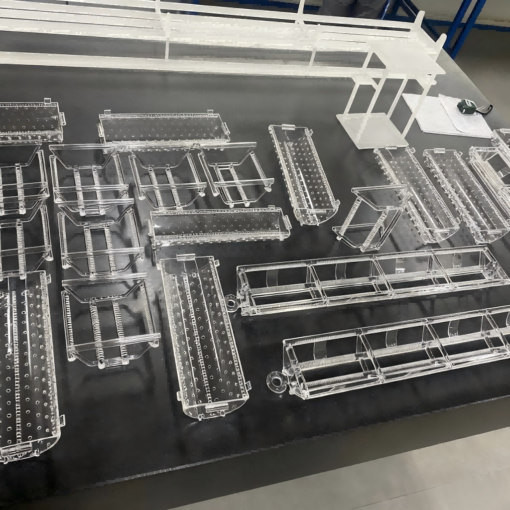
When discussing furnace components, the terms Quartz Boat and Wafer Carrier are often used interchangeably, but in the context of 300mm processing, they refer to the most critically machined component in the furnace. The quartz wafer carrier is the interface between the furnace environment and the silicon wafer. Its job is to hold wafers securely without inducing stress that causes slippage (crystallographic dislocations) or generating particles that kill die yield.
3.1 Why the Wafer Carrier Demands Precision Engineering
Unlike other quartzware that simply contains the process, the quartz boat actively touches the product. Every 300mm wafer rests directly on the carrier. If the wafer carrier design is flawed—if slot pitch varies by more than 0.1mm, if contact points are rough, or if the material contains micro-bubbles at stress points—no amount of temperature tuning will fix the resulting yield loss.
3.2 The Problem: Wafer Slippage and Particle Generation
At elevated temperatures (>950°C), silicon becomes plastic and exhibits viscoelastic behavior. If the quartz boat slots do not support the wafer perfectly evenly, gravity induces slip lines in the crystal lattice—dislocations that propagate along {111} crystallographic planes. These slip lines render the device useless, particularly for logic devices where carrier mobility in the channel region is critical.
Furthermore, any loose fit between the wafer and the boat slot causes micro-fretting as gases flow through the tube at velocities of 10-50 cm/s. This fretting generates silicon and quartz particles ranging from 0.1µm to 10µm in diameter—precisely the size range that causes killer defects in sub-10nm nodes.
For 300mm wafers, the mass is significant enough that even a 0.2mm deviation in slot pitch can create stress points exceeding 1 MPa at the contact interface, sufficient to initiate slip at 1050°C.
3.3 The Solution: Precision Slot Machining and Metrology
This is why the dimensional accuracy of the Quartz Boat / Wafer Carrier slots is paramount. For 300mm processing, industry leaders demand tolerances within ±0.1mm or tighter for slot pitch, depth, and parallelism . The slots must be precisely spaced to ensure consistent thermal exposure and gas flow across every wafer in the boat.
Key Specifications for Wafer Carriers:
| Parameter | Standard Grade | Precision Grade | Measurement Method |
|---|---|---|---|
| Slot Pitch Uniformity | ±0.15mm | ±0.05mm | Optical comparator or CMM |
| Slot Depth | ±0.10mm | ±0.03mm | Depth gauge microscope |
| Slot Parallelism | 0.10mm over 300mm | 0.03mm over 300mm | Laser interferometry |
| Contact Surface Roughness | Ra < 1.0µm | Ra < 0.4µm | Profilometry |
| Slot-to-Slot Runout | 0.20mm TIR | 0.08mm TIR | Rotational gauge |
3.4 Wafer Carrier Design Architectures
Engineers must choose between two primary structural designs for their quartz wafer carriers, depending on throughput needs and process requirements:
Single-Level Boats:
Often used for R&D, pilot production, or low-volume runs. These carriers hold wafers in a single horizontal row. They have lower thermal mass, allowing for faster ramp-up rates (up to 50°C/min) but lower throughput per batch (typically 25-50 wafers). Single-level boats are preferred for processes where temperature uniformity is extremely critical, as the reduced thermal mass minimizes temperature gradients.
Multi-Level (Vertical Stack) Boats:
Essential for high-volume fabs. These 300mm quartz boats maximize batch size—standard configurations hold 100, 125, or even 150 wafers per run—and improve furnace utilization from 60% to over 90%. However, they require careful computational fluid dynamics (CFD) modeling in their design to ensure every wafer, from the top of the carrier to the bottom, experiences the same gas flow velocity and temperature profile.
Emerging Design: Cantilevered Boats
For advanced nodes requiring extremely low particle levels, cantilevered boat designs suspend the wafers from the sidewalls rather than supporting them from below. This eliminates the "shadow effect" where support rods block gas flow, but requires even tighter mechanical tolerances to prevent sagging over time.
3.5 Material Nuance: Clear vs. Opaque Quartz for Carriers
While clear fused quartz is standard for wafer carriers due to its purity and transparency, you may encounter opaque quartz variants in specific applications:
-
Clear Quartz Carriers: Used for standard diffusion and oxidation. Transparency allows for visual inspection of wafers during loading and enables optical temperature measurement systems to view the wafers directly.
-
Opaque Quartz Carriers: Contains microscopic bubbles (typically 10-100µm diameter) that scatter infrared radiation. In specific applications—particularly rapid thermal processing (RTP) and epitaxial deposition—wafer carriers made from opaque quartz act as thermal diffusers, helping to create more uniform temperature zones at the wafer edges by scattering radiation laterally.
-
Semi-Transparent Carriers: A compromise grade containing fewer bubbles than fully opaque quartz, used when both thermal diffusion and partial visibility are required.
3.6 Handling and Automation Compatibility
Modern 300mm fabs are highly automated, with minimal human intervention. A quartz boat is not just a static holder; it must interface perfectly with automated material handling systems (AMHS):
-
Robotic Handling Pads: Carriers must feature reinforced quartz pads or gripper interfaces that robots can grasp without fracturing the quartz. These pads are typically thickened sections (8-12mm vs. 3-5mm wall thickness) with rounded edges to distribute stress.
-
Identification Markings: Many fabs require laser-marked QR codes, data matrix codes, or serial numbers on the wafer carrier itself for tracking inventory and lifecycle management. These markings must be applied using CO₂ lasers with precise power control to create contrast without inducing micro-cracks that become stress risers.
-
FOUP Compatibility: The carrier must be designed to interface with Front Opening Unified Pods (FOUPs) during loading and unloading, requiring precise datum features that align with automation tooling.
4. Quartz Furnace Tubes and Liners: Maintaining Thermal and Flow Uniformity
While the boat holds the wafers, the Quartz Diffusion Tube is the process chamber itself. It must maintain an ultra-clean barrier between the heating elements and the wafers while facilitating laminar gas flow across the wafer surfaces.
4.1 The Problem: Temperature Deviation
If the wall thickness of the furnace tube varies circumferentially or longitudinally, heat transfer through the quartz will vary accordingly. This creates "hot spots" or "cold spots" along the tube, leading to non-uniform oxide growth across the batch of wafers sitting in the quartz boat.
For gate oxides that are only 10-20 atoms thick (1-2nm for advanced nodes), a temperature variation of just ±2°C can result in oxide thickness variations of ±2-3% , pushing devices outside specification limits.
4.2 The Solution: Wall Thickness Uniformity
Precision quartz tubes must exhibit exceptional wall thickness uniformity. High-end manufacturers utilize four-axis synchronous control systems during fabrication to ensure that even in large 300mm-600mm diameter tubes, wall thickness tolerance is held to within ±0.3mm to prevent elliptical deformation and ensure consistent heat flux .
Industry Standard Tube Specifications:
| Diameter Range | Standard Grade Tolerance | Precision Grade Tolerance |
|---|---|---|
| 100-200mm | ±1.5% of wall | ±0.8% of wall |
| 200-300mm | ±1.2% of wall | ±0.6% of wall |
| 300-450mm | ±1.0% of wall | ±0.4% of wall |
| >450mm | ±0.8% of wall | ±0.3mm absolute |
4.3 The Role of Quartz Baffle Disks (Bubbles)
Often overlooked, the Quartz Baffle Disks (also known as bubbles, flow equalizers, or diffuser plates) are critical components of the gas delivery system. Placed at the gas inlet end of the tube, they serve two functions:
-
Flow Laminarization: They diffuse the incoming process gas from a turbulent jet (Reynolds numbers >4000) into a smooth, laminar flow (Re <1000) across the surface of the wafers.
-
Thermal Conditioning: The baffle disks pre-heat the incoming gas to near-process temperature, preventing cold gas from impinging directly on the leading wafers in the boat.
Without proper baffle design, the wafers closest to the gas source would receive a much higher concentration of reactant, ruining uniformity. Advanced baffle systems use multiple disks with progressively larger hole diameters to create a pressure drop that forces gas to distribute uniformly across the tube cross-section.
4.4 Sealing the System: Flanges and Ground Joints
To maintain vacuum (down to 10⁻⁶ Torr for some processes) or controlled atmospheres (from 0.1 Torr to atmospheric pressure), the tube must seal perfectly against the furnace door or end cap. This is achieved through precision-ground Quartz Flanges:
-
Ball Joints: Spherical ground surfaces that allow slight angular misalignment (up to 3°) while maintaining a seal. Used in less critical applications or where thermal expansion differences require flexibility.
-
Flat Ground Joints: Precision-lapped flat surfaces (flatness < 2 helium light bands, approximately 0.5µm) that achieve vacuum-tight seals when compressed against PTFE, silicone, or metal gaskets.
-
Conical Joints: Tapered surfaces (typically 1:10 taper) that self-center and provide large sealing areas for high-vacuum applications.
For ultra-high purity applications requiring minimal outgassing, the sealing surfaces are lapped to optical flatness and sealed directly against silicon gaskets or soft metal (copper or aluminum) gaskets .
5. Addressing the "Creep" Factor: The Battle Against Sag
If you have worked with horizontal furnaces, you know the dreaded "sag." Over time, at continuous high temperatures, quartz tubes and even the support rods of large wafer carriers begin to deform under their own weight—a phenomenon known as creep deformation or viscous flow.
5.1 The Science of Creep
Creep rate is highly dependent on two factors: temperature and the impurities (or dopants) within the quartz structure. At temperatures above 1000°C, amorphous silica behaves as a viscous liquid, albeit with extremely high viscosity (10¹⁴ to 10¹⁵ poise). The rate of deformation follows the Arrhenius relationship:
Deformation Rate∝e−Ea/RTDeformation Rate∝e−Ea/RT
Where E_a is the activation energy for viscous flow—approximately 120-150 kcal/mol for fused silica.
The primary structural factor affecting viscosity is the Hydroxyl (OH) content:
-
High OH Quartz (150-1000 ppm): Typically produced by flame fusion of natural quartz crystals. The presence of OH groups breaks the silicon-oxygen network (Si-O-Si + H₂O → 2 Si-OH), reducing network connectivity and lowering viscosity. At 1100°C, high-OH quartz can have viscosity 10-100x lower than low-OH material.
-
Low OH Quartz (<30 ppm, premium grades <5 ppm): Produced by electrical fusion of natural quartz or by chemical vapor deposition (synthetic quartz). The absence of OH creates a fully connected three-dimensional network of silica tetrahedra, maximizing viscosity and creep resistance.
5.2 Quantitative Impact on Tube Life
The practical impact is dramatic. Consider a horizontal furnace tube of 300mm diameter, 2.5 meters length, supported at the ends:
-
High-OH Quartz (150 ppm): At 1150°C, sag rate ≈ 0.5mm per 100 hours. Tube reaches unacceptable sag (>5mm) in approximately 1000 hours (42 days) of operation.
-
Low-OH Synthetic Quartz (<10 ppm): At 1150°C, sag rate ≈ 0.05mm per 100 hours. Tube reaches unacceptable sag in approximately 10,000 hours (14 months) of operation.
10x improvement in lifetime through OH content control alone.
5.3 Annealing and Stress Relief
Beyond OH content, proper annealing is critical for creep resistance. During fabrication, quartz components develop thermal stresses due to uneven cooling. If these stresses are not relieved, they add to the gravitational stress and accelerate creep.
The annealing process involves:
-
Heating the fabricated component to the annealing point (~1150°C for fused silica)
-
Holding for sufficient time (typically 1-4 hours depending on wall thickness)
-
Slow cooling (1-5°C per minute) through the annealing range
Properly annealed components exhibit <5nm/cm of birefringence when viewed under polarized light, indicating minimal residual stress.
6. Field Guide: Common Failure Modes and Root Cause Analysis
Even with optimal material selection, quartzware eventually fails. Understanding failure modes enables proactive replacement before batch loss occurs.
6.1 Devitrification (Crystallization)
Phenomenon: Quartz transitions from amorphous glass to crystalline cristobalite, appearing as white or gray spots on the surface. The cristobalite layer eventually spalls (flakes off), generating particles.
Root Cause: Alkali metal contamination (Na, K from handling or furnace atmosphere) catalyzes crystallization at high temperatures. The process accelerates above 1000°C and in the presence of water vapor.
Impact on Process: Cristobalite has a different CTE than amorphous quartz (17×10⁻⁶/°C vs. 0.55×10⁻⁶/°C). During cooldown, the crystalline layer contracts more than the substrate, generating tensile stresses that cause micro-cracking and particle release.
Mitigation Strategy:
-
Use quartz with <1ppm alkali metals
-
Implement clean handling protocols (gloves, clean tools)
-
Consider periodic dilute HF etching to remove nascent crystalline layers before they spall
6.2 Creep and Sag (Viscous Deformation)
Phenomenon: Gradual downward deflection of horizontal tubes or bending of boat support rods.
Root Cause: Gravitational stress + high temperature + high OH content (see Section 5).
Impact on Process: Wafer tilt within the boat disrupts gas flow patterns, causing thickness non-uniformity. Severe sag (>5mm) can cause wafers to contact each other or the tube wall.
Quantitative Replacement Criteria:
-
Tube sag >5mm or >0.15% of length
-
Boat rod deflection >0.5mm over 500mm span
-
Wafer tilt >0.1° relative to horizontal
6.3 Warpage (Thermally-Induced Distortion)
Phenomenon: Non-uniform dimensional change, typically causing boats to twist or tubes to go out-of-round.
Root Cause: Excessive heating/cooling rates (>20°C/min) creating temperature gradients >50°C across the component. Also caused by design features that create stress concentrations (sharp corners, sudden thickness changes).
Impact on Process: Warped boats cannot be loaded reliably by automation; warped tubes cause non-uniform heating.
Prevention:
-
Follow manufacturer ramp rate specifications (typically <10°C/min for large components)
-
Require stress analysis (FEA) for custom designs
-
Inspect new components for annealing marks
6.4 Etching and Thinning
Phenomenon: Progressive reduction in wall thickness due to chemical reaction with process gases.
Root Cause:
-
HCl etching: In high-temperature HCl cleans, chlorine reacts with SiO₂ to form volatile SiCl₄, removing quartz at rates of 0.1-1.0µm per hour.
-
Ammonia etching: In nitride deposition, NH₃ reacts with SiO₂ to form silicon nitride and water, gradually consuming the quartz.
Impact on Process: Thinning reduces mechanical strength and eventually leads to failure. Non-uniform etching creates localized weak points.
Monitoring: Measure wall thickness at inlet (most severe etching) during every maintenance cycle.
7. Process-Specific Selection Strategies
Different processes impose different demands on quartzware. Optimizing for your specific process extends life and improves uniformity.
7.1 Dry Oxidation (O₂ ambient)
Demands: Moderate. Pure oxygen is relatively benign to quartz.
Recommendation: High-purity synthetic quartz (OH <30ppm) for tubes; precision-grade clear quartz for boats.
Expected Life: 12-24 months depending on temperature.
7.2 Wet Oxidation (H₂O ambient)
Demands: Severe. Steam accelerates OH incorporation into quartz, increasing creep rate. Steam also accelerates devitrification in the presence of contaminants.
Recommendation: Must use low-OH synthetic quartz (<10ppm). Consider thicker walls (+20%) to extend life.
Expected Life: 6-12 months—approximately half that of dry oxidation.
7.3 Polysilicon Deposition (LPCVD, SiH₄)
Demands: Very severe. Silicon deposits on all quartz surfaces. The deposited poly-Si film has CTE of 2.6×10⁻⁶/°C vs. 0.55×10⁻⁶/°C for quartz. During cooldown, this CTE mismatch generates compressive stress in the quartz, leading to fracture.
Recommendation:
-
Use "sacrificial" liners that can be replaced economically
-
Consider SiC-coated quartz boats—the coating prevents silicon adhesion and enables periodic HF stripping without damaging the quartz
-
Design for periodic cleaning cycles (every 25-50 runs)
Expected Life: 50-200 runs without coating; 500+ runs with SiC coating.
7.4 Silicon Nitride Deposition (LPCVD, SiH₂Cl₂ + NH₃)
Demands: Extreme. Ammonia attacks quartz chemically. The deposited nitride film creates even higher stress than poly-Si due to its high intrinsic stress (up to 1 GPa tensile).
Recommendation:
-
Highest-purity synthetic quartz only
-
SiC coating is essential for long life
-
Expect to replace tubes annually even with optimal selection
7.5 High-Temperature Anneals (>1150°C)
Demands: Extreme. Approaching the softening point of quartz (1200°C for short-term use).
Recommendation:
-
Electrically fused synthetic quartz only (lowest OH)
-
Opaque quartz for improved temperature uniformity
-
Thicker walls (5-6mm vs. 3-4mm standard) for mechanical stability
-
Expect limited life (3-6 months) and plan accordingly
8. Beyond Price: Building a Quartzware Cost of Ownership (CoO) Model
For procurement managers and fab directors, the lowest-priced quartzware is rarely the most economical. This section provides a quantitative framework for evaluating true cost.
8.1 The CoO Formula
Cost of Ownership=Acquisition Cost+Replacement Cost+Yield Loss CostService Life (runs)Cost of Ownership=Service Life (runs)Acquisition Cost+Replacement Cost+Yield Loss Cost
Where:
-
Acquisition Cost: Purchase price + shipping + qualification testing
-
Replacement Cost: Labor for installation + requalification runs + lost production time
-
Yield Loss Cost: Value of wafers lost × additional defect rate attributable to quartzware
-
Service Life: Number of production runs before replacement
8.2 Real-World Example: Quartz Boat Selection
Consider a 300mm fab running 100,000 wafers per month in 25-wafer batches (4,000 batches/month). Batch value: $150,000 (25 wafers × $6,000 estimated value at that process step).
Option A: Standard Natural Quartz Boat
-
Acquisition Cost: $800
-
Service Life: 200 batches (approximately 1.5 months at 4,000 batches/month)
-
Particle Adders: +5 particles/wafer >0.1µm
-
Yield Impact: 1% additional defect density → 1% of batches affected → 40 batches/month × $150,000 × 12 months = $720,000/year yield loss
Option B: Precision Synthetic Quartz Boat
-
Acquisition Cost: $1,800
-
Service Life: 600 batches (4.5 months)
-
Particle Adders: +1 particle/wafer >0.1µm
-
Yield Impact: 0.2% additional defect density → 8 batches/month × $150,000 × 12 months = $144,000/year yield loss
Option C: SiC-Coated Premium Boat
-
Acquisition Cost: $3,500
-
Service Life: 1,500 batches (11 months)
-
Particle Adders: +0.2 particles/wafer >0.1µm
-
Yield Impact: 0.05% additional defect density → 2 batches/month × $150,000 × 12 months = $36,000/year yield loss
8.3 Five-Year Cost Comparison
| Cost Component | Option A | Option B | Option C |
|---|---|---|---|
| Boat Acquisitions (5 years) | 40 boats @ $800 = $32,000 | 13 boats @ $1,800 = $23,400 | 5 boats @ $3,500 = $17,500 |
| Yield Loss (5 years) | $3,600,000 | $720,000 | $180,000 |
| Installation Labor (5 years @ $500/change) | $20,000 | $6,500 | $2,500 |
| Total 5-Year Cost | $3,652,000 | $749,900 | $200,000 |
Conclusion: The premium SiC-coated boat, despite costing 4x more upfront, delivers 18x lower total cost than the standard option over five years.
9. Quality Assurance Checklist
Before accepting any quartz component for your 300mm fab, implement this technical inspection protocol:
9.1 Dimensional Certification Report
-
Verify slot spacing (boats) using optical comparator or CMM—demand ±0.05mm for critical applications
-
Verify wall thickness (tubes) at minimum 8 points around circumference and 5 positions along length
-
Confirm outer diameter (OD) tolerance: ±1.0% for standard, ±0.5% for precision
-
Request runout measurements for rotational symmetry
9.2 Visual Inspection
-
Examine under intense fiber-optic illumination (fiber light guide) at 10x magnification
-
Look for:
-
Bubbles >0.1mm in critical areas (slots, sealing surfaces)
-
Cracks or "chatter marks" from machining
-
Surface roughness or tool marks in wafer contact areas
-
Inclusions or opaque spots
-
9.3 Annealing Quality (Stress Inspection)
-
View component between crossed polarizers or using strain inspection apparatus
-
Properly annealed quartz shows <50nm/cm birefringence
-
Rainbow patterns indicate residual stress—reject if visible to naked eye
9.4 Purity Analysis
-
Request Certificate of Analysis (CoA) with:
-
Total metals <10ppm (synthetic) or <50ppm (natural)
-
Individual alkali metals (Na, K) <1ppm each
-
OH content measurement (FTIR method): <30ppm for standard, <10ppm for premium
-
Transition metals (Fe, Cu, Ni) <0.1ppm each
-
9.5 Surface Finish
-
Measure contact surfaces using profilometer:
-
Ra <0.4µm for wafer slots
-
Ra <0.8µm for non-contact surfaces
-
-
Verify fire-polished edges on all wafer slots
10. Conclusion: Engineering Economics
Selecting quartzware is an exercise in engineering economics. The upfront cost difference between a standard-grade quartz boat and a high-precision, synthetic-grade boat with SiC coating is often less than $3,000—compared to the $150,000 value of a single lost batch of 300mm wafers.
The right quartzware—characterized by tight dimensional tolerances (≥±0.05mm), low OH content (<10ppm) for creep resistance, verified thermal uniformity (wall thickness ±0.3mm), and appropriate coatings for your specific process—directly impacts your fab's profitability. It reduces particle defects, extends maintenance intervals from months to years, and ensures that every wafer in the boat receives the same thermal budget.
As you qualify your next set of components for your diffusion furnaces, look beyond the material and demand the data. Your process yield depends on it.
Contact us today for a competitive quote and technical support!
Let Yichou help you achieve excellence in your next project. Whether you need raw materials, custom alloy solutions, or precision-manufactured components, our team is ready to assist.
- Email us: [email protected]
- Call us/whatsapp: +86 13355741031
- Chat with us: Live chat support available on our website