Meta Description: Looking for a spindle motor for metal milling? Learn how torque curves, angular contact bearings, and rigidity requirements differ when machining aluminum, brass, and steel.
Author: [YICHOU] Engineering Team — application engineers with 15+ years in motor spindle design for CNC metal cutting.
Introduction: The Real Reason Wood Spindles Die on Steel
A 2.2 kW water-cooled spindle rated at 24,000 RPM is one of the most popular choices for CNC routers cutting wood, plastic, and occasionally aluminum. It costs a few hundred dollars, runs on a standard VFD, and delivers excellent surface finish on non-ferrous materials. Then the operator tries to mill a pocket in mild steel, and within minutes the spindle stalls, the tool chatters, and the bearings begin to howl.
This failure is not a matter of “bad luck” or “cheap Chinese parts.” It is a predictable outcome of three engineering mismatches: torque delivery at low speed, bearing load capacity, and thermal stability under continuous metal cutting loads.
Key Takeaway (Direct Answer): Metal milling requires high torque at lower RPMs, along with high-rigidity angular contact bearings, differing significantly from high-RPM wood engraving spindles. While aluminum and brass favor high-speed motor spindles (12,000–24,000 RPM), steel and tough alloys demand specialized low-speed, constant-torque electric spindles paired with rigid spindle nose configurations.
This guide is written for machine builders, job shop owners, and integrators who need to specify a spindle that will survive production metal cutting—not just engrave a few aluminum signs.
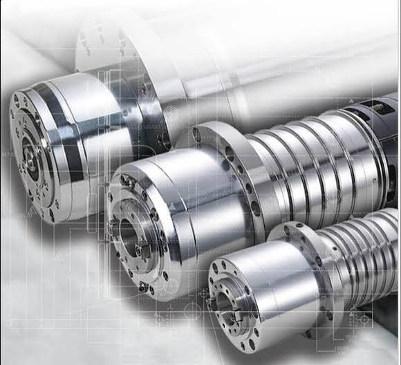
The Metal-Specific Spindle Selection Matrix
The table below synthesizes recommended spindle configurations based on common industrial practice and manufacturer specifications for each material group. Treat it as a starting filter, not a final specification—tool diameter, depth of cut, and machine rigidity will refine the choice.
| Target Material | Recommended Spindle Type | RPM Range | Bearing Configuration | Collet / Taper | Key Selection Factor |
|---|---|---|---|---|---|
| Aluminum (6061 / 7075) | High-Speed Motor Spindle | 12,000 – 24,000 | Hybrid ceramic / matched pairs | ER20 / ER25 / ISO20 | High SFM and chip evacuation |
| Brass & Bronze | Medium/High-Speed Spindle | 10,000 – 18,000 | 70 series angular contact | ER20 / BT30 | Chatter-free surface finish |
| Mild Steel & Cast Iron | High-Torque Electric Spindle | 3,000 – 9,000 | Steel triplex/quadruplex set | BT30 / ISO30 / HSK-F63 | Constant torque at low RPM |
| Stainless / Titanium | Low-Speed Geared or Direct Spindle | 1,500 – 6,000 | Heavy-duty angular contact | BT40 / HSK-A63 | Axial and radial rigidity |
Why the steel and stainless rows look so different: A spindle optimized for aluminum finishing needs small, light balls and a 15° contact angle to run cool at 20,000 RPM. A spindle for steel needs large balls, a 25° contact angle, and often a 4-pole motor winding to produce usable torque at 3,000–6,000 RPM. These are fundamentally different machines, not different “settings” on the same machine.
Deep Dive 1: Torque vs. Speed — The Physics That Kills Wood Spindles
The Two-Zone Torque Curve
Every AC motor spindle operates on a torque-speed curve divided into two regions:
Constant torque zone: From zero to base speed, the motor produces roughly constant torque. The magnetic flux is at full strength, and the drive maintains a constant V/Hz ratio. For a typical 2-pole woodworking spindle rated at 24,000 RPM (400 Hz), this zone ends somewhere between 6,000 and 8,000 RPM.
Constant power zone: Above base speed, torque falls inversely with RPM while power remains roughly constant. This is ideal for wood and aluminum, where small chip loads at high surface footage are the norm.
The problem is arithmetic. If a 2.2 kW spindle produces its rated power at 24,000 RPM, the available torque at 3,000 RPM—assuming the VFD can even maintain flux at that frequency—is a fraction of the nameplate value. In practice, a standard 2-pole spindle run at 3,000 RPM with a conventional V/Hz drive may deliver well under 1 Nm, which is insufficient for even a 6 mm carbide end mill in mild steel.
The VFD Trap and the 4-Pole Solution
Lowering the drive frequency does not increase torque. It weakens the magnetic field and causes the motor to stall under load. There are two legitimate approaches to getting usable torque at metal-cutting speeds:
Option A: A 4-pole spindle. A 4-pole motor produces approximately twice the torque of a 2-pole motor at the same RPM and power rating, because torque is proportional to the number of magnetic poles for a given stator geometry. A 4-pole spindle rated at 12,000 RPM maximum will have a base speed around 3,000–4,000 RPM, placing the constant-torque zone squarely in the steel-milling range. Many industrial motor spindles for metal cutting use 4-pole or even 6-pole designs for this reason.
Option B: Field-oriented control (FOC) VFD. An FOC drive actively decouples the motor’s flux and torque components, maintaining magnetizing current at low speeds even as the frequency drops. This partially compensates for the torque loss of a 2-pole spindle, but it cannot overcome the fundamental magnetic design limits. An FOC drive on a wood spindle will improve low-speed performance, but it will not turn a 24,000 RPM engraving spindle into a steel-milling spindle.
Practical rule: If the spindle’s nameplate maximum speed is 24,000 RPM and it is a 2-pole design, assume it is not suitable for routine steel milling regardless of the VFD.
Deep Dive 2: Bearings — Where Rigidity Is Won or Lost
Why Deep Groove Bearings Fail in Metal
Deep groove ball bearings are the default in low-cost wood spindles. They handle radial loads well and are cheap to produce. But metal milling generates combined loads: the end mill pushes radially (sideways) while also pulling axially (downward during plunge or helical interpolation). Under axial load, a deep groove bearing’s balls ride up the raceway groove, changing the contact angle and causing skidding, heat, and eventual seizure.
Angular Contact: 15° vs. 25°
Angular contact bearings are designed with a defined contact angle between ball and raceway, enabling them to support combined radial and axial loads. The angle choice is a trade-off:
-
15° contact angle: Optimized for speed. Lower friction, less heat at high RPM, excellent radial rigidity. Standard for aluminum finishing spindles. Limited axial capacity.
-
25° contact angle: Optimized for rigidity and axial load. The steeper angle provides greater axial stiffness and resistance to tool push-off. Standard for steel and cast iron milling. Slightly higher heat generation at very high speeds.
Bearing arrangements: Metal-cutting spindles rarely use single bearings at the nose. Duplex (DB/DF) pairs provide preload and tilt resistance. Triplex or quadruplex sets distribute load across a wider area and are mandatory for heavy steel milling, where the spindle nose must resist deflection under high radial and axial forces.
Hybrid Ceramic: Not Just for Aluminum
Hybrid ceramic bearings (steel races, silicon nitride balls) are commonly specified for high-speed aluminum spindles because the lighter balls reduce centrifugal force and friction heat. But their benefits extend to metal cutting generally: lower thermal growth, longer grease life, and higher limiting speeds. For a spindle that will run 8,000 RPM in steel for hours, ceramic balls reduce the heat that would otherwise migrate into the spindle shaft and shift the Z-axis zero point.
Deep Dive 3: Thermal Growth and the Tolerance Band
The Z-Axis Shift Problem
Metal cutting generates heat in three places: the cutting zone, the motor stator, and the bearings. That heat causes the spindle shaft (typically steel) to expand axially, pushing the tool downward relative to the workpiece. Simultaneously, the housing expands. The net result is a drift in tool tip position that can easily exceed 0.02–0.05 mm within the first hour of operation—enough to consume the entire tolerance band on a precision pocket or bore.
Wood routers ignore this because wood tolerances are measured in tenths of a millimeter. Metal parts are not so forgiving.
Water Cooling and Chiller Precision
Air-cooled spindles rely on a fan pushing ambient air over the housing. This is adequate for intermittent wood cutting but insufficient for continuous metal removal, where the motor and bearings generate heat faster than air can carry it away.
Water-cooled spindles circulate coolant through a jacket around the stator and bearing housings. For precision metal milling, the chiller must hold coolant temperature within ±1°C. A fluctuation of a few degrees causes the spindle to “breathe” in and out, making tight tolerances impossible to hold. Closed-loop refrigeration chillers are standard on production metal-cutting spindles for this reason.
Sealing: The Last Line of Defense
Metal chips are abrasive. Flood coolant is corrosive. If either reaches the bearings, failure follows quickly. High-quality metal spindles use a combination of labyrinth seals and air purge at the nose. The labyrinth creates a tortuous path that chips cannot easily traverse, while positive air pressure inside the spindle blows stray particles away from the bearing cavity. This is not optional equipment on a spindle that will see cast iron dust or aluminum chips at 15,000 RPM.
Tool Holding: ER vs. BT vs. HSK
ER Collets: Adequate for Aluminum, Limited for Steel
ER collets (ER16, ER20, ER25) are ubiquitous because they are inexpensive, flexible, and accept a wide range of shank diameters. For high-speed aluminum machining on a router or light-duty spindle, an ER20 or ER25 collet with a balanced nut is perfectly serviceable. Runout of 0.01–0.02 mm is typical and acceptable for many non-ferrous applications.
However, ER collets have limits. Clamping force is lower than a taper interface. At high RPM, a poorly balanced ER chuck introduces vibration that damages surface finish and bearing life. And for steel milling, the rigidity of the tool-spindle interface becomes critical—an ER collet simply cannot match the stiffness of a BT30 or HSK taper.
BT30 and HSK: The Production Standard
For any machine intended to cut steel or run unattended with an automatic tool changer, a taper interface is required.
BT30: A 7:24 steep taper. Robust, inexpensive, and rigid enough for low-speed, high-torque cutting. The workhorse of entry-level VMCs. Limitation: single-contact taper design means centrifugal expansion at high RPM reduces grip stiffness. Not ideal above roughly 10,000 RPM.
HSK (HSK-F63, HSK-A63): A hollow shank taper with simultaneous face and taper contact. At high speed, centrifugal force causes the hollow shank to expand outward, tightening its grip on the spindle taper—the opposite of BT behavior. This makes HSK the standard for high-speed machining and precision metal work, with repeatability in the single-digit micron range and superior radial rigidity.
Frequently Asked Questions
Q1: Can I mill aluminum with a standard high-speed spindle motor?
A: Yes, with appropriate tooling and chip evacuation. A water-cooled spindle operating at 12,000–24,000 RPM with an ER20 collet and single- or two-flute aluminum-specific end mills works well for 6061 and 7075. The critical requirements are adequate cooling (water, not air, for continuous cutting) and effective chip removal to prevent built-up edge.
Q2: What is the best spindle motor for metal milling when cutting steel?
A: A high-torque electric spindle with a 4-pole (or 6-pole) motor, 25° angular contact bearings in a triplex or quadruplex arrangement, and a BT30 or HSK tool interface. Speed range should cover 3,000–8,000 RPM with usable torque in the constant-torque zone. A standard 2-pole wood spindle, even with an FOC drive, is not a substitute.
Q3: Why are angular contact bearings essential for metal cutting spindles?
A: Deep groove bearings support primarily radial loads. Metal milling generates simultaneous radial and axial loads—the tool is pushed sideways and pulled downward. Angular contact bearings are designed with a contact angle that allows them to support both load directions without skidding or losing preload. A 25° contact angle is preferred for steel because it prioritizes axial rigidity.
Q4: Can I use a 2.2 kW spindle to cut steel with very light passes?
A: You can scratch shallow engravings into mild steel with a 1–2 mm carbide tool and extremely conservative parameters, but it is neither productive nor reliable. The spindle will operate far outside its designed torque zone, the bearings will experience loads they were not specified for, and tool life will be poor. For any regular steel cutting, specify a spindle with a low-speed torque curve and appropriate bearings.
Q5: Air-cooled or water-cooled for metal milling?
A: Water-cooled for any continuous metal cutting. Air cooling is sufficient for intermittent aluminum work on a router, but steel and stainless cutting generates heat continuously. A water-cooled spindle with a chiller holding ±1°C is the minimum for holding tolerances on metal parts.
Conclusion: Three Pillars, One Decision
Selecting a spindle motor for metal milling is not a search for the “best” spindle. It is an exercise in matching three engineering parameters to your material and production requirements:
-
Torque at the speed you will actually run. A 24,000 RPM spindle is useless for steel if its torque curve collapses below 8,000 RPM. Check the constant-torque zone, not just the nameplate power.
-
Bearing capacity for combined loads. 15° angular contact for aluminum speed; 25° for steel rigidity. Duplex minimum; triplex for heavy cuts.
-
Thermal stability for the tolerance you need to hold. Water cooling and ±1°C chiller control are mandatory for precision metal work.
A spindle that compromises on any one of these pillars will fail in production—not immediately, but predictably, usually in the middle of a job with a deadline.
Need a spindle specified for your material and tolerance requirements?
As a direct manufacturer, we engineer motor spindles with matched angular contact bearing sets (15° and 25° configurations), G0.4 dynamic balancing, liquid cooling with integrated thermal management, and BT30/HSK interfaces for production metal cutting.
[Download Our Metal Milling Spindle Specification Guide] or [Consult Our Application Engineers] to discuss your specific material, tooling, and tolerance requirements.
Get in Touch with Yichou
- Email us: [email protected]
- Call us/whatsapp: +86 13355741031
- Chat with us: Live chat support available on our website