Introduction: The Gravitational Tax That Defines Drone Performance
In commercial UAVs and industrial robotics, weight is not just a specification—it is the singular variable that determines endurance, payload capacity, and operational profitability. Every unnecessary gram of structural deadweight directly reduces battery life, shortens range, and lowers return on investment for fleet operators. The commercial drone market is growing rapidly, driven by autonomous delivery, agricultural scanning, and infrastructure inspection—applications where every minute of flight time matters.
Achieving structural efficiency is not only about carbon fiber monocoques. It is fundamentally about how we manufacture the load-bearing metal elements: motor mounts, gimbal brackets, folding arm hinges, landing gear pivots, and payload latches. These components demand metallic strength in tension, shear, and fatigue that composites alone cannot always provide.
This article addresses the core dilemma facing UAV and robotics OEMs: when should designers rely on 5‑axis CNC drone parts hogged from solid billet, and when should they switch to net‑shape metal injection molding components that mass‑produce intricate geometries at scale? By examining technical, economic, and performance trade‑offs—and quantifying where the crossover points lie—this guide provides a decision framework for building lighter, stronger, and more commercially viable unmanned aerial systems.
.jpg)
Chapter 1: 5‑Axis CNC Machining – Ultimate Lightweighting for Low Volumes and Prototypes
5‑axis CNC machining optimizes commercial UAV weight during low‑volume production by enabling complex pocketing and topological optimization on solid Aluminum 7075 or Titanium Grade 5. It achieves ultra‑thin walls (under 1 mm) and complex organic geometries without costly up‑front tooling, delivering exceptional strength‑to‑weight ratios for prototype validation and fleet customization.
1.1 Pocketing and Ribbing: Engineering High Strength‑to‑Weight Ratios from Solid Billets
The fundamental advantage of 5‑axis CNC machining lies in removing material exactly where it is not needed. Combined with topology optimization software, 5‑axis machining sculpts components that follow load paths with surgical precision, achieving weight reductions of 40‑60% compared to conventionally designed parts while maintaining structural rigidity.
With two additional rotational axes compared to 3‑axis mills, 5‑axis machines can approach a part from almost any direction, cutting deep cavities, undercuts, and contoured surfaces in a single setup. This eliminates multiple fixture errors and positional tolerance stack‑ups. For UAV applications, this translates directly into lighter, more efficient geometries. A custom‑machined drone arm bracket from 7075‑T6 aluminum can achieve exceptional strength‑to‑weight ratios, reducing overall airframe weight without compromising integrity under dynamic flight loads.
Advanced 5‑axis CNC centers reliably achieve wall thicknesses down to 0.5 mm in aluminum, with micro‑machining systems capable of 0.3 mm features. For gimbal housings, camera yokes, and motor mount webs, these thin sections directly extend flight endurance. However, thin‑wall machining demands sophisticated toolpath planning and deformation control. Experienced programmers use roughing with conservative stock, stress‑relieving heat treatments for titanium, and finish passes with reduced radial engagement to maintain accuracy.
1.2 Material Performance: Unleashing Full Mechanical Properties of Forged Aluminum 7075‑T6 and Titanium Grade 5
Materials machined from solid billet inherit the full characteristics of the parent alloy: uniform grain structure, consistent properties, and no porosity—advantages that near‑net‑shape processes struggle to match.
Aluminum 7075‑T6 remains the workhorse for UAV structural components. With tensile strength of approximately 570 MPa and exceptional strength‑to‑density ratio, it offers mechanical performance comparable to mild steel at one‑third the weight. When 5‑axis machined, 7075‑T6 achieves surface finishes down to Ra 0.6 μm and dimensional tolerances of ±0.01 mm, enabling precision interfaces for bearings and motor shafts.
Titanium Grade 5 (Ti‑6Al‑4V) delivers 900‑950 MPa tensile strength with density 60% higher than aluminum but significantly lower than steel. Its exceptional fatigue strength, fracture toughness, and corrosion resistance make it ideal for high‑cycle loading, thermal cycling, or marine exposure. However, titanium’s low thermal conductivity and chemical reactivity demand specialized machining parameters—rigid workholding, reduced cutting speeds, and high‑pressure coolant.
The critical advantage of 5‑axis CNC over near‑net‑shape alternatives is zero porosity and full density. For fatigue‑critical applications such as motor mounts subjected to continuous vibration and cyclic thrust, this structural integrity directly translates into service life and safety margins.
1.3 Financial Breakthrough: When 5‑Axis CNC Drone Parts Overcome Tooling Costs (1 to 500 units)
The economic case for CNC machining hinges on no dedicated tooling = no upfront capital. For volumes from single prototypes to approximately 500 units, CNC is almost always the most economical route.
For a typical 50 g stainless steel UAV component:
-
At 500 pieces/year, CNC costs ~$28.00/part, MIM ~$18.50/part + tooling amortization → CNC wins.
-
At 2,000 pieces, CNC ~$25.00/part, MIM ~$9.20/part + tooling → CNC still favorable.
-
Above ~5,000–10,000 pieces, MIM’s per‑part economics overtake CNC (MIM ~$3.50/part at 10,000 units vs. CNC ~$22.00/part).
For expensive materials like titanium, where MIM achieves >95% material utilization versus CNC’s 30‑70% yield, the crossover volume can drop to 2,000‑3,000 pieces. For simple geometries with minimal machining time, CNC can remain competitive well beyond 10,000 units.
For quantities under 500 units, the absence of mold costs (typically $5,000‑$20,000 for a production‑grade MIM tool) makes 5‑axis CNC the clear winner for UAV prototyping and fleet customization.
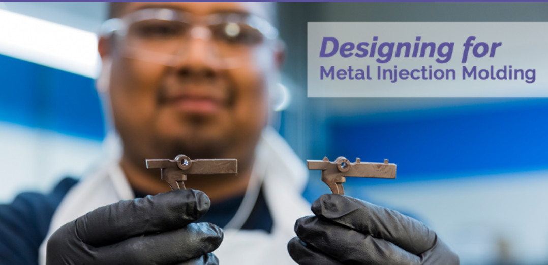
Chapter 2: Metal Injection Molding (MIM) – Mass‑Producing Miniature, High‑Strength Structural Complexities
Metal Injection Molding (MIM) is the ideal process for mass‑producing complex, ultra‑light UAV and robotic parts weighing under 100 g. By blending fine metal powders with a thermoplastic binder, MIM produces intricate, net‑shape internal geometries and micro‑joints with up to 98% sintered density, making traditional CNC cutting cost‑prohibitive at scale.
2.1 Sintered Geometry Mastery: Intricate Micro‑Hinges, Gear Trains, and Gimbal Mounts
MIM combines the geometric freedom of plastic injection molding with the mechanical properties of sintered metals. Fine metal powders (<20 μm) mixed with a thermoplastic binder create a feedstock that flows like molten plastic into precision molds. The “green part” is debound and sintered (1,200‑1,400 °C) to 95‑98% density, developing full mechanical strength.
Unlike CNC machining—which is limited by tool access—MIM can produce features that are impossible or prohibitively expensive to machine: undercuts, internal threads, knurled surfaces, and lattice‑like internal structures, all formed net‑shape. For UAVs, this means folding arm locking mechanisms can integrate complex cam profiles, detent features, and spring seats in a single component. Micro‑gear trains for gimbal actuation can include integral hubs, keyways, and tooth forms with minimal post‑processing.
Typical MIM part size is under 200 mm, with ideal weights below 100 g—perfectly aligned with UAV hardware: motor mounts (5‑30 g), gimbal brackets (10‑50 g), and locking mechanism components (2‑20 g). For these miniature but geometrically complex parts, MIM offers a manufacturing solution that CNC cannot economically match at scale.
2.2 High‑Volume Economics: Transitioning from CNC to MIM Above 2,000 Pieces
MIM injection molds typically range from $5,000 to $20,000 depending on cavity count, complexity, and material requirements. For volumes under 1,000 parts, CNC avoids this upfront investment. But as quantities scale, the economics invert.
At 10,000 pieces, MIM parts typically cost $0.10‑$5.00 each, while CNC‑machined equivalents run $2.00‑$50.00. For a 10‑20 g stainless steel UAV component, per‑part savings at 10,000 units can exceed $15‑20—quickly recovering the tooling investment.
The crossover point (where MIM becomes cheaper than CNC) is typically between 5,000 and 15,000 pieces, varying with part complexity and material cost. For complex geometries requiring multiple setups or expensive materials like titanium, the crossover can occur as low as 2,000‑3,000 pieces.
Equally important is total cost of ownership. MIM parts emerge from sintering as net‑shape components, often requiring only minimal secondary operations (bead blasting, vibratory finishing, or chemical polishing). CNC‑machined parts may need deburring, drilling, tapping, and multiple inspections—each adding cost and lead time.
2.3 How Optimized Materials Reduce Commercial UAV Weight via MIM: Titanium and Stainless Steel 17‑4 PH Powders
Stainless Steel 17‑4 PH (precipitation‑hardening) is particularly well‑suited to UAV structural components. It achieves high strength (tensile up to 1,100‑1,300 MPa after heat treatment) combined with good corrosion resistance and fatigue properties. MIM 17‑4 PH parts can be sintered to 96‑98% density and heat treated to near‑wrought properties. For locking mechanisms, latch cams, and gear train components, it offers an optimal balance of strength and processability.
Titanium Ti‑6Al‑4V MIM represents the frontier of lightweight manufacturing. With density 4.43 g/cm³ (56% that of steel) and specific strength exceeding most steel alloys, titanium is the ultimate lightweight structural material. Advanced MIM facilities use vacuum sintering furnaces with controlled partial pressures to prevent contamination, achieving 97‑98% density and properties approaching wrought Ti‑6Al‑4V. High material cost ($35‑50/kg) makes MIM’s >95% material utilization especially compelling.
Designers must consider the trade‑off between MIM’s material efficiency and surface finish / tolerances. Sintered MIM parts typically achieve Ra 1.0‑3.0 μm, compared to CNC’s Ra 0.2‑0.8 μm. Tolerances for MIM are ±0.3‑0.5% of nominal dimension, whereas CNC routinely achieves ±0.01‑0.05 mm. For bearing fits or sealing interfaces, secondary finishing may be required. For most UAV structural hardware, as‑sintered MIM surfaces are entirely adequate.
Chapter 3: Head‑to‑Head Comparison – 5‑Axis CNC vs. MIM for UAV Hardware
A deeply analytical engineering framework for procurement managers.
| Design Metric | 5‑Axis CNC Machining | Metal Injection Molding (MIM) | UAV Design Impact |
|---|---|---|---|
| Optimal Production Volume | 1–5,000 units | 5,000–100,000+ units | Forecast fleet size before process selection |
| Minimum Wall Thickness | 0.2–0.5 mm | 0.5–1.0 mm | CNC enables thinner, lighter walls |
| Material Waste & Buy‑to‑Fly Ratio | 30–70% waste | >95% utilization | MIM dramatically reduces waste for expensive materials |
| Upfront Tooling CapEx | Low (no mold) | $5,000–$20,000 (mold) | CNC for low volume; MIM requires volume amortization |
| Geometric Freedom | Limited by tool access | Very high – undercuts, internal passages | MIM for miniaturized mechanisms; CNC for larger beams |
| Surface Finish (Ra) | 0.2–1.6 μm | 1.0–3.0 μm (as‑sintered) | CNC for bearing surfaces; MIM may need secondary finishing |
| Typical Tolerance | ±0.01–0.05 mm | ±0.3–0.5% of dimension | CNC for precision fits; MIM acceptable for most interfaces |
| Lead Time (Prototype to First Article) | 1–3 weeks | 4–6 weeks (includes mold) | CNC enables faster iteration |
| Material Range | Any machinable metal | Powdered alloys (stainless, Ti, tool steels) | CNC broader; MIM limited to powder‑available alloys |
| Part Size Limit | Unlimited (within machine travel) | ~200 mm, optimal <100 g | CNC for large airframes; MIM for micro‑components |
Chapter 4: Application Blueprint – Mapping the Drone to the Right Process
Where to Use 5‑Axis CNC Machining
Airframe Structural Beams and Spars
Long‑span components (200‑800 mm) requiring high rigidity. MIM’s size limit (~200 mm) makes it unsuitable. CNC from 7075‑T6 billet delivers the span while using pocketing and ribbing to remove non‑load‑bearing material.
Heavy‑Duty Motor Mounts for High‑Thrust Applications
In heavy‑lift drones (5‑20 kg payload), motor mounts experience extreme thrust loads (50‑200 N per motor) plus thermal cycling. These require zero porosity, excellent thermal conductivity, and tight tolerances. CNC‑machined 7075‑T6 or titanium Grade 5 delivers fully dense material and precision bearing fits. Small errors in bolt pattern or flatness can cause oscillations, accelerated bearing wear, and “jello” video artifacts—so CNC is mandatory.
Prototype and Low‑Volume Fleet Hardware
For programs under 500 units, CNC avoids a $5,000‑20,000 MIM mold. This applies to custom military drones, specialized agricultural platforms, and early‑stage startups. CNC also enables rapid design iteration—revised geometry in days, not weeks.
Where to Use Metal Injection Molding (MIM)
Folding Arm Locking Mechanisms
Many commercial delivery drones use folding arms for compact storage. Locking mechanisms require cam surfaces, spring seats, detent pockets, and latch features—3‑5 functions in one part. MIM produces these as a single net‑shape component, eliminating assembly steps. 17‑4 PH stainless steel provides thousands of reliable cycles.
Payload Release Latches and Micro‑Gears
Delivery mechanisms for medical supplies, food, and parcels need reliable latches, pawls, and micro‑gears (2‑15 mm) with complex tooth forms and undercuts. MIM molds miniature gears with integral hubs and precise tooth profiles—features extremely time‑consuming to machine.
Camera Gimbal Brackets and Yokes at Volume
When scaling from 100 prototypes to 10,000 production units, gimbal brackets shift decisively to MIM. These often have complex organic shapes to minimize airflow disturbance while providing rigid camera mounting. MIM produces net‑shape components with consistent properties, reducing assembly fit issues and inspection burden.
Chapter 5: High‑Conversion FAQ Segment
(Targeting Google Featured Snippets & engineering inquiries)
Q1: How exactly do optimized materials reduce commercial UAV weight without sacrificing structural safety?
A: Weight reduction is achieved by using high specific‑strength alloys—Aluminum 7075‑T6 (570 MPa at 2.81 g/cm³) and Titanium Grade 5 (950 MPa at 4.43 g/cm³)—combined with topology optimization software. Topology optimization automatically places material only where load paths flow, removing mass from low‑stress regions. For UAVs, this means motor mounts, arm brackets, and gimbal housings can be lightened by 30‑50% while maintaining safety factors above 2.0 under maximum thrust and gust loads. The result is thin‑walled, pocketed geometries that preserve stiffness where needed and eliminate gravitational tax elsewhere.
Q2: What is the surface roughness comparison between 5‑axis CNC machined and sintered MIM drone parts?
A: 5‑axis CNC achieves as‑machined Ra 0.2‑1.6 μm (precision finishing Ra 0.4‑0.8 μm). Sintered MIM parts typically have Ra 1.0‑3.0 μm. For bearing journals, seal interfaces, or cosmetic finishes, CNC is superior and ready to use. For most UAV structural components, as‑sintered MIM surfaces are adequate, though secondary finishing (bead blasting, vibratory polishing) can improve them. CNC is mandatory when Ra < 0.8 μm is required.
Q3: What is the minimum wall thickness achievable for UAV components using each process?
A: For 5‑axis CNC machining of aluminum: practical minimum 0.5 mm, micro‑machining down to 0.3 mm. Titanium requires slightly thicker (0.6‑0.8 mm) due to higher cutting forces. For MIM: typical minimum 0.5‑1.0 mm depending on material and geometry; thinner walls risk incomplete mold filling or sintering warpage. For ultra‑lightweight applications demanding walls under 0.5 mm (e.g., camera gimbal webs), CNC is the only viable process.
Q4: At what production volume does MIM become more cost‑effective than 5‑axis CNC for UAV parts?
A: The crossover is typically between 5,000 and 15,000 pieces annually, depending on part complexity, material cost, and tolerances. For a typical 50 g stainless steel component: at 500 pieces, CNC is cheaper; at 10,000 pieces, MIM is significantly cheaper ($3.50 vs. $22.00 per part). For titanium, where raw material is expensive and MIM achieves >95% material utilization vs. CNC’s 30‑70%, the crossover can drop to 2,000‑3,000 pieces. Request a DFM analysis from your manufacturing partner for a specific crossover calculation.
Q5: Can YICHOU handle the transition from CNC machined drone prototypes to full‑scale mass MIM production?
A: Yes. YICHOU bridges the scalability gap. Our 5‑axis CNC machining centers validate prototype designs in 7‑15 days with tolerances down to ±0.005 mm and surface finishes suitable for functional testing. Once your design is production‑ready and volumes justify it, we seamlessly transfer the geometry to our in‑house MIM tooling and sintering furnaces. With annual MIM capacity exceeding 200 tons and ISO 9001 certification, we serve drone, aerospace, medical, and defense OEMs. Our single‑source approach eliminates the friction of transferring designs between separate suppliers, reducing lead time and ensuring material property continuity.
Conclusion & Call to Action (CTA)
The commercial UAV market is growing rapidly. For drone and robotics OEMs, market leadership will be determined not only by software or battery chemistry, but by fundamental manufacturing decisions. Every gram saved through intelligent process selection extends flight endurance. Every dollar optimized through appropriate volume strategy improves margins. Every geometry enabled by the right method unlocks new missions.
The choice between 5‑axis CNC and MIM is not binary—it is a lifecycle continuum:
-
Prototype with CNC – validate fit, form, and function without mold investment.
-
Pilot with CNC – build early fleet data and refine design.
-
Scale with MIM – once volume economics justify the transition.
The most successful drone hardware programs understand where each process excels and when to move between them.
The YICHOU Fleet Advantage: YICHOU (www.nbyichou.com) offers rare dual capability—advanced multi‑axis CNC machining for precision prototyping and low‑volume production, alongside high‑density Metal Injection Molding (MIM) tooling and sintering furnaces for high‑volume scalability. Our 5‑axis machining centers achieve ±0.005 mm tolerances and thin‑wall features down to 0.3 mm, processing aerospace‑grade aluminum 7075, titanium Ti‑6Al‑4V, stainless steel 17‑4 PH, and specialty alloys. MIM production exceeds 200 tons annually, serving clients who need consistent, repeatable high‑volume manufacturing. With ISO 9001 certification, comprehensive CMM inspection (0.001 mm accuracy), and engineering teams experienced in UAV structural design, YICHOU provides the technical partnership that moves your drone program from concept to certified flight hardware.
Direct RFQ Anchor: Designing a next‑generation delivery drone airframe, tactical robot arm, or commercial inspection platform? Send your STEP files to YICHOU today for an instant DFM review and weight‑optimization analysis from our aerospace engineering team. Contact [email protected] or visit www.nbyichou.com to begin your lightweighting journey.
The sky is not the limit—it is the operating environment. Make every gram count.
Get Quote
- Visit our website: https://www.nbyichou.com/
- Email us: [email protected]
- Call us/whatsapp: +86 13355741031
- Chat with us: Live chat support available on our website