Understanding precision machining tolerances is essential for engineers, designers, and procurement professionals seeking to optimize component specifications for manufacturing efficiency and cost-effectiveness. The tolerance specified for each dimension directly impacts manufacturing complexity, inspection requirements, tooling costs, and ultimately the total cost of machined components. This comprehensive technical guide explains international tolerance standards, geometric dimensioning and tolerancing (GD&T), and practical guidelines for specifying tolerances that balance functional requirements with manufacturing capability.
The proper application of tolerances distinguishes between designs that are impractical to manufacture and those that can be produced efficiently at competitive cost. Overly tight tolerances increase manufacturing difficulty and cost without providing functional benefit, while excessively loose tolerances may compromise assembly or performance. Understanding how to specify tolerances appropriately is a fundamental skill for anyone involved in component design or procurement. This guide covers the major tolerance standards used worldwide, their appropriate applications, and practical recommendations for optimizing tolerance specifications.
Understanding Dimensional Tolerances
Dimensional tolerances define the acceptable variation in the size or location of a feature, specifying how much larger or smaller a dimension may be while remaining acceptable for assembly and function. Tolerances are typically expressed as a nominal dimension followed by the allowable deviation, such as 25.00 +0.05/-0.00 mm, indicating the dimension must fall between 25.00 mm and 25.05 mm. The tolerance range selected should reflect the minimum variation necessary for proper function while maximizing manufacturing flexibility and minimizing cost.
General tolerance standards provide default tolerance values for features where specific tolerances are not indicated on drawings, simplifying drawing preparation and ensuring consistent acceptable quality across features. The most widely applied general tolerance standard is ISO 2768, which defines tolerance classes for linear dimensions, angular dimensions, and geometric tolerances. This standard and its regional equivalents (such as DIN 2768 in Germany and JIS B 0405 in Japan) enable international standardization of general tolerance requirements on manufacturing drawings.
The relationship between tolerance and cost is approximately exponential, meaning that each successive level of precision requires substantially more manufacturing effort and cost. Reducing tolerance from ±0.5 mm to ±0.1 mm may increase cost by 20-30%, while tightening from ±0.1 mm to ±0.02 mm might increase cost by 100% or more. Understanding this relationship helps designers specify tolerances that are no tighter than necessary for function, optimizing total cost without compromising product quality.
ISO 2768 General Tolerance Standard
ISO 2768 is the international standard for general tolerances on linear and angular dimensions without individual tolerance indications, providing four tolerance classes with progressively tighter ranges. The standard consists of two parts: ISO 2768-1 covers linear and angular dimensions, while ISO 2768-2 addresses geometric tolerances for features without individual indications. This two-part structure enables separate specification of dimensional and geometric tolerance requirements to match manufacturing capabilities with design requirements.
The tolerance classes in ISO 2768 are designated by letters representing tolerance levels: f (fine), m (medium), c (coarse), and v (very coarse). For linear dimensions, the m class (medium) allows deviations such as ±0.1 mm for dimensions up to 6 mm and ±0.3 mm for dimensions from 30-120 mm. The f class provides approximately half the tolerance of m, while c and v classes provide progressively larger tolerances for less critical features.
For CNC machining applications, ISO 2768-m is the most commonly applied general tolerance class, providing precision suitable for most assembled components while remaining achievable with standard machining operations. The f class may be specified for precision applications requiring tighter fits or enhanced accuracy, though this increases manufacturing costs. The c class is appropriate for rough machining or features where tight tolerance is unnecessary, while v class is rarely used in precision manufacturing.
Geometric Dimensioning and Tolerancing (GD&T)
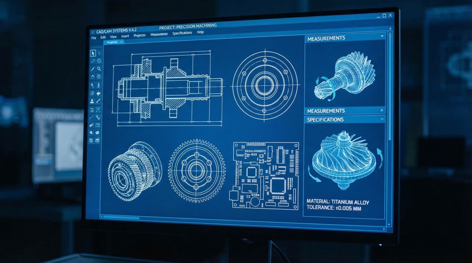
Geometric Dimensioning and Tolerancing (GD&T), defined by ASME Y14.5 in North America and ISO 1101 internationally, provides a comprehensive system for specifying geometric tolerances on technical drawings. Unlike simple dimensional tolerances, GD&T defines controls for form, orientation, location, and runout of features, enabling precise specification of functional requirements while maximizing manufacturing tolerance. The system uses feature control frames to indicate the type of geometric control, the tolerance zone definition, and any applicable datum references.
The geometric characteristic symbols include straightness, flatness, circularity, cylindricity for form control; parallelism, perpendicularity, angularity for orientation control; position, concentricity, symmetry for location control; and circular runout, total runout for runout control. Each characteristic defines a specific type of geometric variation that must be controlled, enabling designers to specify exactly which geometric variations affect function without over-constraining manufacturing.
Datum features establish reference frames from which geometric tolerances are measured, ensuring consistent interpretation across manufacturing and inspection operations. Proper datum selection is critical for achieving functional assembly requirements, as the relationship between mating components depends on consistent reference surfaces. Datums should be selected based on functional requirements, with primary datum providing the most critical reference, secondary datum controlling a perpendicular relationship, and tertiary datum completing the reference frame.
Common Tolerance Classes for CNC Machining
CNC machining typically achieves tolerances ranging from ±0.005 mm (0.0002 inch) for precision operations to ±0.5 mm (0.020 inch) for rough machining, with standard CNC practice normally achieving ±0.02-0.05 mm (±0.001-0.002 inch) consistently. Understanding typical achievable tolerances helps designers specify appropriate requirements without over-constraining manufacturing. The following ranges represent general guidelines for standard CNC machining capabilities under normal conditions.
Standard machining tolerance for most CNC operations is typically ±0.02 mm (±0.0008 inch) for dimensions and ±0.01 mm position tolerance for features. This tolerance is achievable with standard CNC equipment using appropriate tooling and programming, providing good fit for most assembled components without requiring special processes or extended cycle times. Features requiring this tolerance level can typically be produced at standard pricing without premium charges.
Precision machining tolerance of ±0.005 mm (±0.0002 inch) requires enhanced equipment capability, specialized tooling, controlled environmental conditions, and potentially additional inspection procedures. This tolerance level is appropriate for precision fit applications, aerospace components, medical devices, and optical equipment. Components requiring this level of precision typically command premium pricing due to the specialized capability and extended processing time required.
Tolerance Specification Best Practices
Effective tolerance specification balances functional requirements with manufacturing capability and cost considerations through systematic evaluation of each dimension's importance to assembly and performance. Critical dimensions that affect fit, function, or safety should receive tight tolerances reflecting their functional importance, while non-critical dimensions should use general tolerances to minimize cost. Over-tolerancing non-critical features wastes money without providing functional benefit.
Reference manufacturing capabilities early in the design process, ideally during design for manufacturability (DFM) review, to identify specifications that may cause manufacturing difficulty or excessive cost. Design specifications should account for typical manufacturing variation, not theoretical perfect conditions. Collaboration between design engineering and manufacturing engineering during specification development helps optimize tolerance selections for the production environment.
Consider the cumulative effect of tolerance stack-up in assemblies where multiple dimensions affect fit or function. The worst-case analysis method assumes all dimensions are at their tolerance limits simultaneously, while statistical analysis accounts for normal distribution of variations. Understanding tolerance stack-up helps specify appropriate tolerances for individual components to ensure reliable assembly without excessive cost.
Surface Finish and Roughness Tolerances
Surface finish specifications complement dimensional and geometric tolerances by controlling the microscopic texture of machined surfaces. Surface roughness, typically measured in micrometers (Ra), affects friction, wear, sealing, painting, and aesthetic appearance. Common surface roughness values for machined surfaces range from Ra 0.8 μm (32 μin) for general machined surfaces to Ra 0.2 μm (8 μin) for precision applications, with optical surfaces requiring Ra below 0.1 μm.
Standard machined surfaces from CNC operations typically achieve Ra 1.6-3.2 μm (63-125 μin) depending on tooling, speeds, feeds, and material. Additional processing such as grinding, lapping, or polishing can achieve Ra 0.2-0.8 μm for precision applications. The transition between machining and finishing operations represents a significant cost step, making appropriate surface finish specification important for cost control.
The relationship between surface roughness and manufacturing cost is exponential, similar to dimensional tolerances. Improving surface finish from Ra 3.2 μm to Ra 1.6 μm may require reduced cutting speeds and finer tooling, increasing cost by 30-50%. Further improvement to Ra 0.8 μm typically requires grinding or specialized finishing, potentially doubling or tripling the machining cost. Surface finish specifications should match actual functional requirements to avoid unnecessary expense.
Working with Your Machining Partner
Effective communication of tolerance requirements ensures your machining partner clearly understands specifications and can deliver components meeting your expectations. Drawings should include complete tolerance information, either through specific tolerances on critical dimensions or reference to general tolerance standards for non-critical features. Avoid mixing specific tolerances with general tolerance references, which creates confusion about which specification applies to each dimension.
Provide background on functional requirements when tolerances seem unusually tight or unusual, helping your supplier understand the application context. This information enables the supplier to suggest alternative approaches, recommend tolerance modifications based on manufacturing experience, or confirm capability to meet requirements. Open communication prevents misunderstandings that could result in rejected parts or costly re-work.
Establish inspection and verification requirements early, particularly for precision components where statistical process control or detailed inspection reports may be required. Understand what measurement equipment and methods the supplier uses, and specify any special requirements such as calibrated instruments, environmental conditions, or statistical documentation. Clear agreement on inspection requirements prevents disputes and ensures consistent quality verification.
Partner with Yichou for Precision Machining
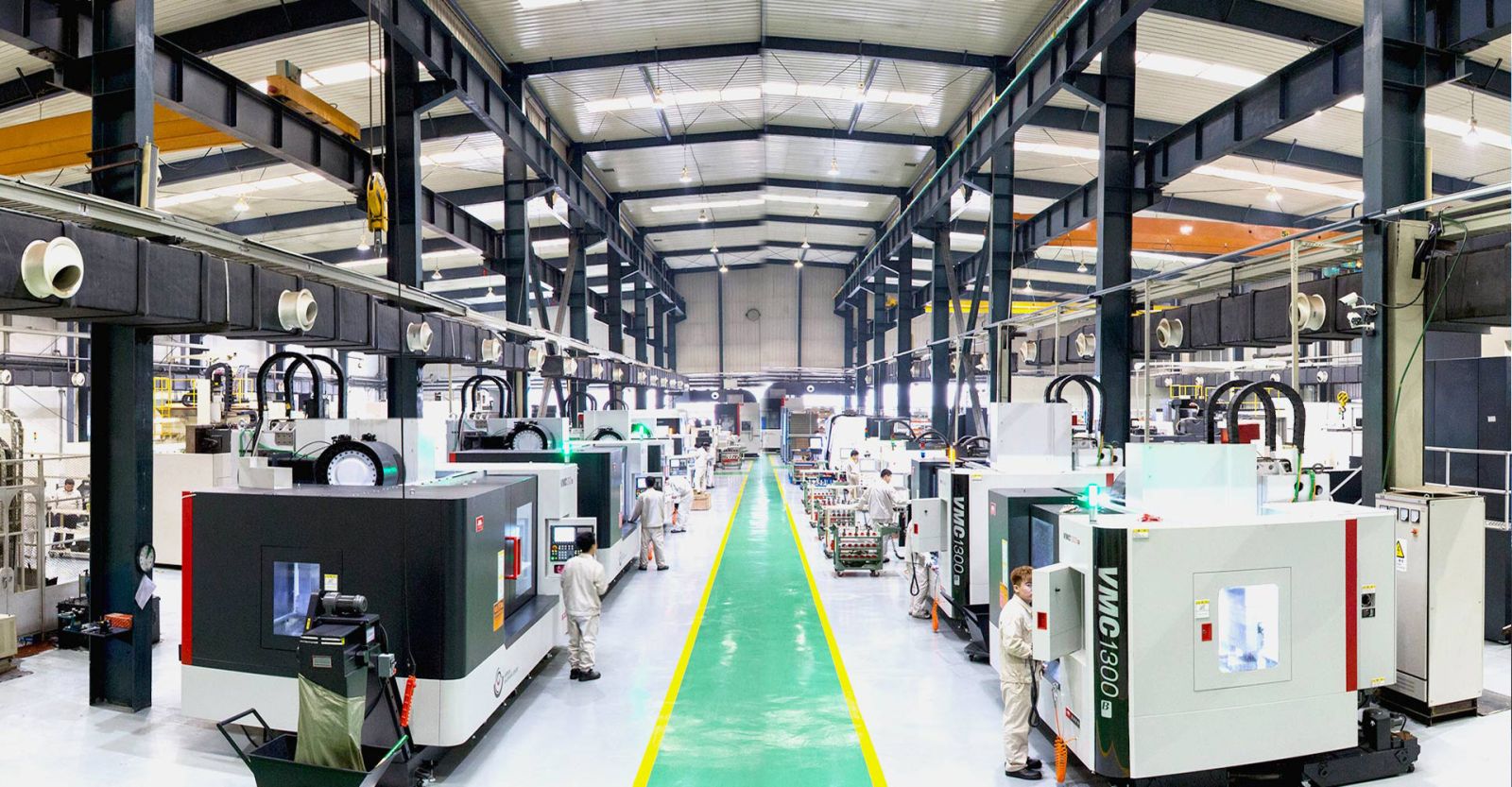
Ningbo Yichou Industrial Co., Ltd. provides comprehensive precision CNC machining services meeting a wide range of tolerance requirements. With over 20 years of experience in precision manufacturing, their team regularly achieves tolerances of ±0.01 mm and tighter for critical applications across aerospace, medical, automotive, and industrial sectors. Their quality systems include comprehensive inspection capabilities with coordinate measuring machines (CMMs), electronic height gauges, and precision surface finish measurement equipment.
Yichou's engineering team provides valuable design for manufacturability feedback to help optimize tolerance specifications for your specific applications. They work with customers to understand functional requirements and recommend appropriate tolerance levels that balance performance with manufacturing efficiency. Their experience across diverse industries enables them to provide practical guidance on specification optimization.
Contact Yichou today to discuss your precision machining requirements. Their knowledgeable team will help you develop appropriate tolerance specifications while delivering quality components that meet your exact requirements on time and at competitive prices.
Contact us today for a competitive quote and technical support!
Let Yichou help you achieve excellence in your next project. Whether you need raw materials, custom alloy solutions, or precision-manufactured components, our team is ready to assist.
- Email us: [email protected]
- Call us/whatsapp: +86 13355741031
- Chat with us: Live chat support available on our website