Introduction
In the relentless pursuit of performance, engineers and designers have turned to a material that defies conventional limitations. Carbon fiber composites offer an unparalleled strength-to-weight ratio, surpassing traditional metals like steel and aluminum by significant margins. With a tensile strength exceeding 3,500 MPa at just one-fifth the weight of steel, carbon fiber has become the cornerstone of modern engineering across automotive, aerospace, industrial robotics, and medical device manufacturing.
However, off-the-shelf components rarely meet the exacting demands of advanced projects. Standard sizes, generic weave patterns, and predetermined wall thicknesses often lead to compromises that undermine performance targets. Whether you are fitting a space-constrained drone, upgrading a classic car with period-correct aesthetics, or prototyping a new industrial machine, stock solutions frequently fall short.
This is where custom carbon fiber engineering becomes essential. Transitioning to bespoke composite solutions empowers you to optimize weight distribution, control fiber orientation for specific load paths, achieve unmatched aesthetic excellence, and ensure perfect integration with existing systems. This comprehensive guide will walk you through every aspect of the custom carbon fiber parts ecosystem—from fundamental material science and tooling concepts to fabrication methods, cost estimation, and selecting the ideal manufacturing partner.
Chapter 1: Understanding Custom Carbon Fiber Manufacturing & Fabrication Processes
The journey from raw material to finished high-performance component is a sophisticated orchestration of chemistry, precision engineering, and quality control. Understanding these processes is fundamental to making informed decisions about your custom project.
1.1 Tooling First: The Critical Role of Custom Carbon Fiber Molds
Every exceptional part begins with an exceptional mold. Tooling represents the foundational investment in any custom carbon fiber manufacturing project, determining part accuracy, surface finish, repeatability, and overall cost-efficiency.
Types of Molds:
-
Composite Tooling (Epoxy-based): These molds offer excellent dimensional stability and low thermal expansion coefficients, making them ideal for low-to-medium production runs (5–50 parts). They are cost-effective for complex shapes and deliver superior surface finishes.
-
Aluminum CNC Molds: Machined from solid aircraft-grade aluminum, these tooling solutions are preferred for high-volume production (50–500+ parts). Aluminum molds offer exceptional durability, rapid heat transfer during curing, and can withstand hundreds of production cycles without degradation.
-
3D-Printed Composite Patterns: For rapid prototyping and proof-of-concept validation, 3D-printed patterns dramatically reduce lead times from weeks to just days. These are typically used for initial fitment testing and design verification before committing to production tooling.
-
Steel Molds: Reserved for extremely high-volume production (1,000+ parts), steel tooling offers maximum durability and dimensional stability but comes with significantly higher upfront costs.
Tooling Selection Matrix:
| Mold Material | Best For | Cycle Life | Relative Cost | Lead Time |
|---|---|---|---|---|
| Composite | Prototypes, small batches | 5–50 parts | Low-Medium | 2–3 weeks |
| Aluminum | Medium-high volume | 50–500 parts | Medium | 3–4 weeks |
| Steel | Mass production | 500–5,000+ parts | High | 4–6 weeks |
| 3D Printed | Concept validation | 1–3 parts | Very Low | 2–5 days |
Cost & Lead Time Considerations:
The upfront investment in custom carbon fiber molds typically ranges from $500 for simple flat patterns to over $10,000+ for complex 3D automotive body panels with intricate undercuts and draft angles. However, this investment is rapidly amortized when scaling to batch production, with per-unit costs decreasing significantly after just 10–20 parts.
1.2 Key Fabrication Methods for Custom Carbon Parts
Different projects demand different manufacturing approaches. Here is a comprehensive technical breakdown of the core methods used to create high-quality custom carbon parts.
Autoclave Processing (Prepreg):
This represents the gold standard for structural perfection and is essential for aerospace, motorsport safety components, and critical load-bearing applications. Pre-impregnated fibers (prepreg) are laid up using precision cut-patterns, vacuum-bagged, and cured under elevated heat (120–180°C) and high pressure (up to 7 bar). This process achieves:
-
Maximum fiber volume fraction (60–65%)
-
Void content below 1% (near-zero defects)
-
Superior interlaminar shear strength
-
Predictable, repeatable mechanical properties
Vacuum Assisted Resin Transfer Molding (VARTM):
Also known as vacuum infusion, this method uses a vacuum to pull catalyzed resin into a dry fiber layup through strategically positioned inlet ports. Benefits include:
-
Ideal for large, complex geometries
-
Reduced labor costs compared to prepreg layup
-
Excellent fiber-to-resin ratio (55–60% fiber volume)
-
Ability to integrate core materials (foam, honeycomb) for stiffness enhancement
Compression Molding & Forged Carbon:
For high-volume applications with intricate 3D shapes and tight production schedules, compression molding and forged carbon offer rapid cycle times (3–10 minutes per part). Chopped fibers or pre-formed charges are placed in heated matched-metal dies and compressed under pressure. Advantages include:
-
Rapid production cycles ideal for automotive interior components
-
Excellent surface finish and dimensional repeatability
-
Automated process suitable for high-volume manufacturing
-
Forged carbon offers unique aesthetic "marble" patterns
5-Axis CNC Machining & Trimming:
Post-curing precision is achieved through advanced machining. 5-axis CNC routers ensure micron-level hole positioning, clean edge routing, and precise surface contouring. Critical applications include:
-
Mounting hole drilling (accurate to ±0.005")
-
Edge trimming and profile routing
-
Surface contouring for aerodynamic profiles
-
Core removal and access hole machining
1.3 Step-by-Step: From CAD to Finished Carbon Fiber Part
Understanding the complete workflow helps you plan timelines and budget accordingly.
Step 1: 3D Modeling & Finite Element Analysis (FEA)
Your journey begins with a 3D CAD model (STEP, IGES, or SolidWorks .SLDPRT formats). For load-bearing applications, FEA simulations optimize fiber orientation and layup schedules to achieve specific stiffness and strength targets while minimizing weight.
Step 2: Tooling Design & Manufacturing
Based on your CAD model, engineers design the mold geometry, accounting for:
-
Material shrinkage (typically 0.1–0.5% depending on resin system)
-
Draft angles (2–5° for easy part removal)
-
Surface finish requirements (textured vs. high-gloss)
-
Parting lines and ejection mechanisms
Step 3: Pattern Cutting & Layup
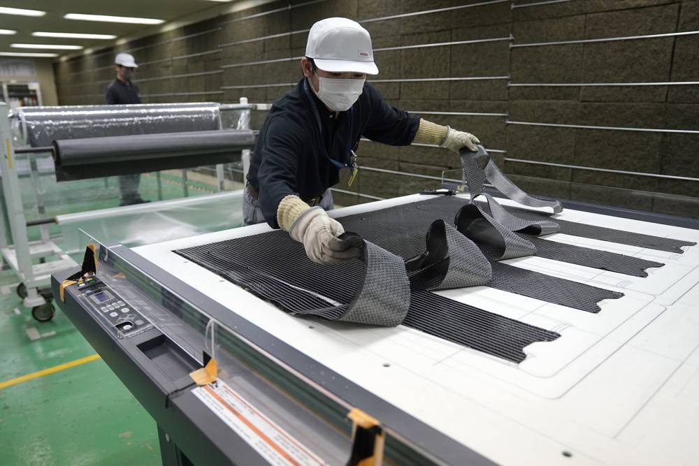
Using automated cutting tables (Gerber or Zund systems), precise fabric patterns are cut from rolls of carbon fiber fabric or prepreg. Trained technicians then lay up the plies according to the engineered schedule, ensuring correct fiber orientation.
Step 4: Curing Process
The layup enters the curing phase:
-
Autoclave: 120–180°C, 6–7 bar pressure, 2–6 hours
-
VARTM: 80–120°C oven cure, 4–12 hours
-
Compression Molding: 150–200°C, 50–100 bar pressure, 3–10 minutes
Step 5: CNC Machining & Surface Finishing
Once cured, the part undergoes precision machining to achieve final dimensions. Surface finishing includes:
-
Sanding and filling (pinhole elimination)
-
Primer application and sanding (400–800 grit progression)
-
Clear coat application (standard or UV-protective automotive grade)
-
Multi-stage polishing for mirror finish
Step 6: Quality Inspection
Every critical part undergoes rigorous quality control:
-
CMM (Coordinate Measuring Machine) inspection for dimensional accuracy
-
Ultrasonic testing for void detection (aerospace applications)
-
Visual inspection for surface defects
-
Bond strength testing (if metal inserts are included)
.jpg)
Chapter 2: Automotive Applications – From Body Panels to Custom Interior Trim
Automotive engineering remains one of the largest drivers of the custom composite industry. The benefits are tangible and measurable, from improved lap times to enhanced fuel efficiency.
2.1 Lightweight Body Construction: Hoods, Panels & Aerodynamics
Weight reduction is the "low-hanging fruit" of performance engineering. Replacing a heavy steel hood with a custom carbon fiber hood can reduce front axle weight by 15–30 pounds (or more depending on vehicle size), dramatically improving steering response, handling dynamics, and weight distribution.
Weight Reduction Impact:
| Component | Original Material | Weight | Carbon Alternative | Weight Savings |
|---|---|---|---|---|
| Hood | Steel | 40 lbs | Carbon fiber | 25–30 lbs |
| Roof panel | Steel | 35 lbs | Carbon fiber | 20–25 lbs |
| Trunk lid | Steel | 30 lbs | Carbon fiber | 18–22 lbs |
| Door panels | Steel | 45 lbs each | Carbon fiber | 30 lbs each |
| Bumper beam | Steel | 25 lbs | Carbon fiber | 15 lbs |
Engineering Considerations:
Designing custom carbon fiber body panels requires addressing several critical factors:
-
UV Resistance: Automotive-grade clear coats with UV inhibitors prevent yellowing and fiber degradation over time
-
Edge Reinforcement: Additional plies at latch points, hinge mounts, and edge boundaries prevent delamination under load
-
Surface Finish: Class-A surface requirements demand specialized tooling and meticulous surface preparation
-
Thermal Expansion: Carbon fiber's near-zero CTE (Coefficient of Thermal Expansion) prevents panel distortion under temperature extremes
For aerodynamic applications, custom carbon fiber car parts like splitters, diffusers, and canards benefit from the material's ability to maintain their shape under high-speed aerodynamic loads.
2.2 Interior Overlays & Cosmetic Trim Integration
The interior is where luxury meets engineering, and custom carbon parts offer a high-end aesthetic that traditional materials cannot match. We engineer molded overlays and direct-replacement interior trim components that preserve OEM functionality while transforming the cabin's aesthetic.
Precision Fitment Process:
-
3D scanning of existing interior components using blue-light structured light scanners (accuracy: ±0.1mm)
-
Digital modeling of the carbon replacement ensuring:
-
Retention of OEM clip engagement points
-
Clearance for HVAC ducts and electrical harnesses
-
Proper airbag deployment paths (for dashboard components)
-
Access to switches, vents, and controls
-
Case Example: C7 Carbon Fiber Dash
We recently engineered a c7 carbon fiber dash overlay for a Corvette C7, covering the center console and gauge cluster. The project required:
-
Matching the OEM's 2×2 twill weave pattern
-
Maintaining visibility of all warning indicators and displays
-
Achieving consistent gloss across a complex compound-curve surface
-
Ensuring proper fitment around the infotainment screen and HVAC controls
The result: a dramatic aesthetic upgrade that enhanced the vehicle's interior while preserving full functionality.
2.3 Precision Small Parts & Accessories
Consumer demand extends to the details. We manufacture a range of aesthetic and functional carbon fiber novelties that allow enthusiasts to personalize their vehicles.
Popular Accessories:
-
Custom carbon fiber license plate frames: Achieve high-gloss, UV-stable clear coats to prevent yellowing during summer months
-
Side mirror covers: Lightweight replacements that reduce turbulence and improve aerodynamics
-
Gauge bezels and instrument clusters: 3D-molded overlays for cockpit personalization
-
Shift knobs and steering wheel trim: Touch surfaces that benefit from carbon's tactile characteristics
-
Engine bay dress-up kits: Cam covers, intake covers, and fuse box covers that showcase mechanical aesthetics
Chapter 3: Structural & Industrial Applications – Tubes, Profiles & Beyond
Beyond sheet goods, custom tubing opens up a world of structural applications spanning robotics, aerospace, medical devices, and industrial automation.
3.1 Custom Carbon Fiber Tubes: Engineering Guide
Hollow cylindrical components are critical for:
-
Drone and UAV arms
-
Robotic arm linkages
-
Bicycle and wheelchair frames
-
Industrial actuator shafts
-
Aerospace wing spars and control rods
Manufacturing Techniques for Tubing:
| Method | Description | Best For | Typical Diameter Range |
|---|---|---|---|
| Roll-Wrapping | Prepreg layers wrapped around mandrel | High flexural rigidity | 0.5"–6" (12–150mm) |
| Filament Winding | Continuous fibers wound at precise angles | Pressure vessels, drive shafts | 2"–24" (50–600mm) |
| Pultrusion | Continuous process for linear profiles | Constant cross-sections | 0.5"–4" (12–100mm) |
Engineering Variables for Carbon Fiber Tubes:
-
Wall Thickness: Typically 0.5mm–5mm depending on load requirements
-
Fiber Orientation: 0° (axial stiffness), ±45° (torsional strength), 90° (hoop strength)
-
Core Integration: Foam or honeycomb cores can enhance stiffness without weight penalty
-
Joint Design: Metal-to-composite bonding requires careful surface preparation and adhesive selection
3.2 Aerospace & Industrial Applications
| Industry | Application | Key Requirements |
|---|---|---|
| Aerospace | UAV arms, satellite booms, antenna support | Thermal stability, low CTE, high stiffness |
| Medical | Prosthetic limbs, surgical instruments | Biocompatibility, sterilizability, lightweight |
| Robotics | End effectors, robot arms | High stiffness-to-weight, low inertia |
| Industrial | Machinery covers, protective housing | Chemical resistance, EMI shielding |
Chapter 4: Material Selection Guide – Choosing the Right Carbon Fiber for Your Project
Selecting the correct material specifications is critical to achieving your performance targets.
4.1 Fiber Grades: Understanding the Differences
| Fiber Grade | Tensile Strength (MPa) | Modulus (GPa) | Application | Cost Factor |
|---|---|---|---|---|
| T300 | 3,500 | 230 | General purpose, automotive | 1× |
| T700 | 4,900 | 230 | Structural, aerospace | 1.5× |
| T800 | 5,500 | 294 | High-performance aerospace | 2.5× |
| M40J | 4,400 | 377 | High modulus (stiffness critical) | 3× |
4.2 Fabric Weaves: Aesthetic & Performance Tradeoffs
| Weave Type | Appearance | Mechanical Characteristics | Best For |
|---|---|---|---|
| Plain Weave | Simple checkerboard | Moderate drape, good stability | Flat panels, cosmetic surfaces |
| Twill Weave (2×2) | Diagonal pattern | Excellent drape, conformability | Complex curves, automotive body |
| Satin Weave (4/8 Harness) | Smooth, glossy | Superior drapability | Extreme contours, tooling |
| Forged Carbon | Marble/random pattern | Good strength, cost-effective | Interior trim, complex 3D shapes |
4.3 Resin Systems: Matching Chemistry to Application
| Resin Type | Temperature Limit | Chemical Resistance | Application |
|---|---|---|---|
| Epoxy | 120–200°C | Excellent | Aerospace, high-performance automotive |
| Vinyl Ester | 100–150°C | Good | Marine, industrial corrosion resistance |
| Polyester | 80–100°C | Fair | General purpose, cost-sensitive |
Chapter 5: Cost Estimation Guide – Budgeting for Custom Carbon Fiber Projects
Understanding cost drivers helps you budget effectively and make informed decisions about your project.
5.1 Cost Breakdown
| Cost Component | Percentage of Total | Typical Range |
|---|---|---|
| Tooling (molds) | 30–50% | $500–$10,000+ |
| Material (fiber, resin) | 20–30% | Varies by grade |
| Labor (layup, curing) | 15–25% | Higher for autoclave work |
| Machining & Finishing | 10–15% | CNC, painting, polishing |
| Shipping & Logistics | 5–10% | International vs. domestic |
5.2 Project Cost References (10-piece batch)
| Project Type | Tooling Cost | Per-Unit Cost (10 pieces) | Total Project Cost |
|---|---|---|---|
| Flat panel (license plate frame) | $300–$800 | $50–$150 | $800–$2,300 |
| Simple hood (2D curve) | $1,000–$2,500 | $200–$400 | $3,000–$6,500 |
| Complex body panel (3D, undercuts) | $2,500–$5,000 | $400–$800 | $6,500–$13,000 |
| Structural tube (roll-wrapped) | $1,000–$3,000 | $80–$250 | $1,800–$5,500 |
Chapter 6: How to Choose the Right Custom Carbon Fiber Manufacturer
Selecting the right partner is as critical as the design itself. Should you search for "custom carbon fiber fabrication near me" or look to a dedicated manufacturer? The table below helps you decide.
| Evaluation Metric | Local Fabrication Shop | Dedicated Export Manufacturer |
|---|---|---|
| Best For | One-off prototypes, local site visits | Scalable production, lower unit costs |
| Lead Times | 1–3 weeks (simple layups) | 3–6 weeks (including mold build) |
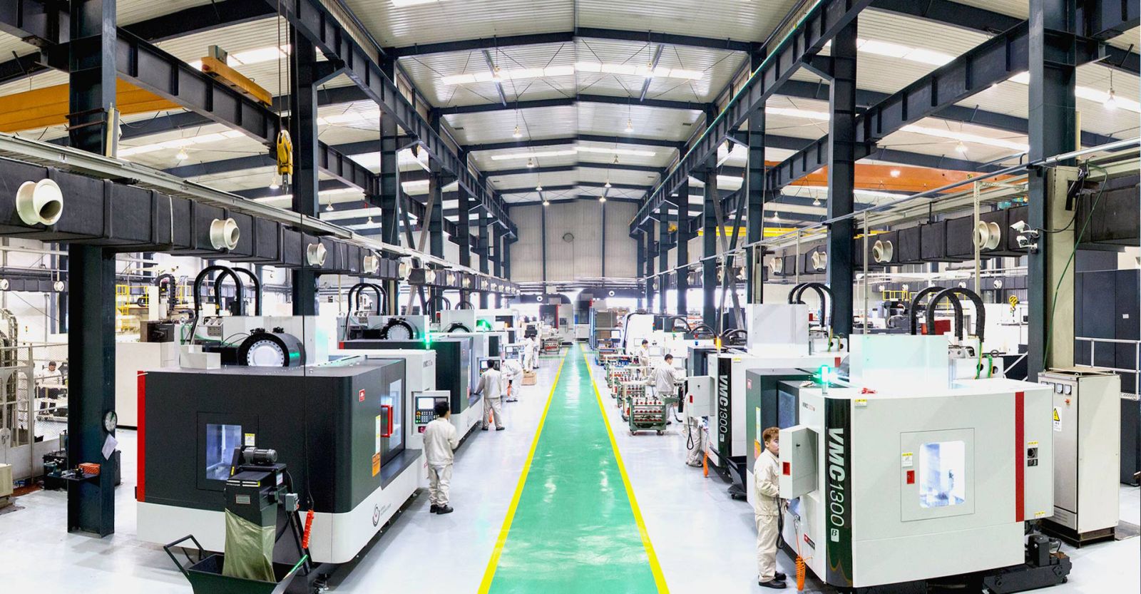
| Equipment Capability | Manual wet layups, 3-axis CNC | Autoclaves, 5-axis CNC, CMM QA |
| Unit Cost at Scale | Higher labor overhead | Optimized material yield, volume pricing |
| Quality Control | Visual inspection only | NDT, ultrasonic, CMM documentation |
| Material Selection | Limited inventory | Full range of aerospace-grade materials |
6.1 Key RFQ Checklist
-
What fiber weaves (twill, plain, forged) and resin systems do you stock?
-
Do you perform in-house CMM and non-destructive testing (NDT)?
-
What are your standard tolerances for CNC-machined carbon composite parts?
-
Can you provide material certificates and source documentation?
-
What is your typical lead time from CAD approval to delivery?
-
Do you offer design for manufacturability (DFM) consultation?
-
What surface finishing options do you provide (paint, clear coat, matte)?
-
Can you handle metal insert integration (threaded inserts, bonding plates)?
Frequently Asked Questions
Q1: How much does it cost to make a custom carbon fiber part?
Costs depend on part dimensions, tooling complexity, material grade, and surface finish requirements. Simple flat parts may cost $50–$150 per unit with tooling starting around $500, while complex automotive body panels can range from $400–$800 per unit with tooling over $5,000. Batch manufacturing significantly amortizes tooling costs—producing 20–50 parts reduces per-unit cost by 40–60%.
Q2: What file formats are required to start custom carbon fiber fabrication?
We prefer 3D CAD files in STEP (.stp), IGES (.igs), or SolidWorks (.sldprt) formats for complex components. These are essential for 5-axis CNC mold machining and structural FEA analysis. For flat sheet applications, simple 2D DXF files are sufficient. For complex surfaces, please provide original design files or high-resolution STL files.
Q3: What is the difference between wet layup and autoclave prepreg custom carbon fiber?
Wet layup involves manually applying liquid resin to dry fabric, curing at room temperature under low vacuum. This process yields a part with 30–40% fiber volume and 2–5% void content, resulting in a heavier part with lower mechanical properties. Autoclave prepreg uses pre-impregnated resin systems cured at 180°C under 7 bar pressure, achieving 60–65% fiber volume and <1% void content. This delivers 2–3× greater strength-to-weight ratio and is mandatory for aerospace and structural automotive applications.
Q4: What fiber weave is best for a custom carbon fiber hood – twill or plain?
Twill weave (2×2) is generally preferred for automotive hoods because it offers excellent drapability over complex curves and hides minor surface imperfections better than plain weave. The diagonal pattern provides a premium aesthetic that's synonymous with carbon fiber. Plain weave is stiffer and less conformable but offers slightly better impact resistance. For most automotive applications requiring Class-A surface finish, twill is the recommended choice.
Q5: Can I paint custom carbon fiber parts?
Yes, but proper preparation is essential. All painted surfaces must be carefully sanded (400–800 grit), primed with an adhesion-promoting primer, and top-coated with automotive-grade urethane paint. For applications where the carbon weave should remain visible, we recommend applying UV-resistant clear coat rather than opaque paint to showcase the material's natural aesthetic while protecting against degradation.
Q6: What is the minimum wall thickness for custom carbon fiber tubes?
The minimum practical wall thickness depends on the tube diameter and fabrication method. For roll-wrapped tubes, wall thickness typically ranges from 0.5mm to 3.0mm. A general guideline: for diameters under 1 inch (25mm), minimum wall thickness is 0.5mm; for 1–3 inch diameters, 1.0–1.5mm; for larger diameters, 2.0mm+. Thinner walls are possible for non-structural applications but become difficult to manufacture without defects.
Q7: Do you offer automotive-grade UV protection for carbon fiber parts?
Yes, all automotive exterior components are finished with UV-stabilized clear coats specifically formulated to protect against solar degradation. These clear coats contain UV absorbers and hindered amine light stabilizers (HALS) that prevent the epoxy matrix from yellowing and protect the carbon fibers from becoming brittle. For maximum longevity, we recommend ceramically sealed clear coats that offer 5+ years of UV resistance.
Q8: How do I maintain my carbon fiber parts?
Maintaining carbon fiber parts is straightforward: wash with mild automotive soap and water using a soft microfiber cloth, avoid harsh chemical cleaners and abrasive compounds, apply a quality automotive wax or sealant every 3–6 months for UV protection, and inspect mounting points and edges periodically for signs of wear or delamination. Avoid using pressure washers near edges or bonded joints as high-pressure water can cause edge delamination over time.
Q9: What is the difference between dry carbon and wet carbon?
These industry terms describe the manufacturing method. Dry carbon refers to prepreg components cured in an autoclave—"dry" because the resin is pre-impregnated and requires no additional wet resin during layup. Wet carbon describes parts made through manual wet layup where resin is applied during fabrication. Dry carbon components typically offer superior mechanical properties, lighter weight, and better surface finish. However, wet carbon can be cost-effective for prototypes or non-structural applications where ultimate performance isn't critical.
Q10: What is the lead time for custom carbon fiber body panels?
For custom body panels requiring new tooling, the complete timeline typically ranges from 4–8 weeks, broken down as follows: tooling design and manufacturing (2–3 weeks), sample part production and fitment validation (1–2 weeks), and final production run plus shipping (1–2 weeks). For existing tooling or simple designs without complex curves, lead times can be reduced to 2–4 weeks. Expedited services are available for critical projects with compressed timelines.
Conclusion
Custom carbon fiber engineering represents the intersection of material science, precision manufacturing, and design innovation. Whether you're seeking the structural integrity of an autoclave-cured aerospace component, the aesthetic sophistication of a custom automotive interior, or the functional performance of a lightweight industrial part, the possibilities are limited only by engineering imagination.
The key to successful projects lies in understanding the complete ecosystem—from material selection and tooling investment to fabrication methods and quality assurance. By partnering with an experienced manufacturer who offers comprehensive DFM consultation, you can navigate these complex decisions with confidence.
Ready to transform your CAD models into high-performance reality? Contact our engineering team today to submit your drawings for a free DFM (Design for Manufacturability) review and competitive quote. Our experts will analyze your design, recommend optimal material selection, provide detailed cost estimates, and establish a realistic production timeline. Let's bring your custom carbon fiber vision to life.
Get Quote
- Visit our website: https://www.nbyichou.com/
- Email us: [email protected]
- Call us/whatsapp: +86 13355741031
- Chat with us: Live chat support available on our website