1. Introduction
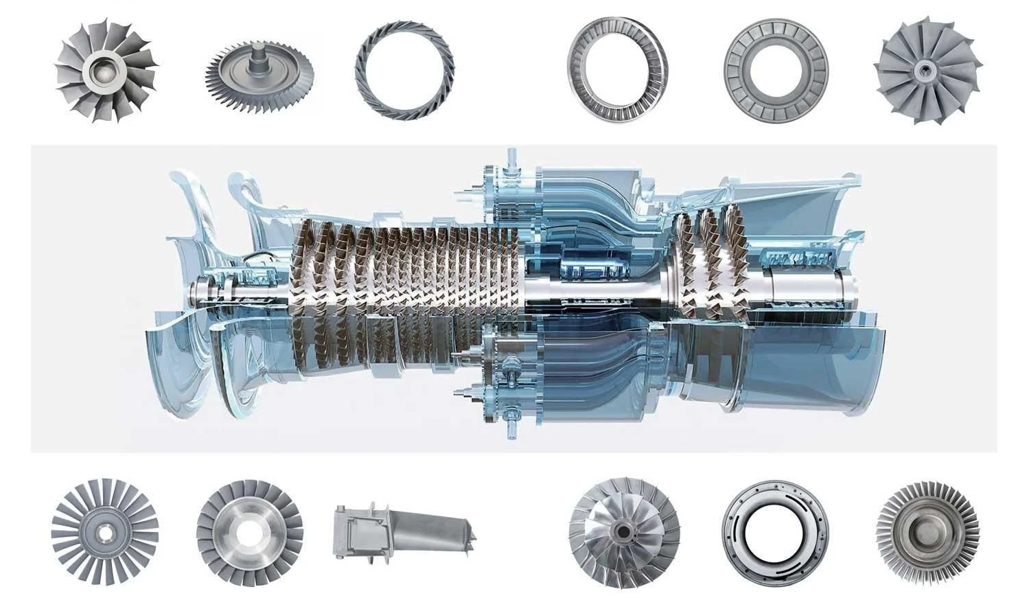
Inconel is a family of nickel-chromium-based superalloys known for their exceptional strength and resistance to extreme temperatures, corrosion, and oxidation. These properties make Inconel a preferred material for high-stress applications, particularly in aerospace, power generation, and oil & gas industries. One of the most critical uses of Inconel is in gas turbine engines, where components must withstand intense heat and mechanical stress over prolonged periods.
Key gas turbine parts made from Inconel include:
-
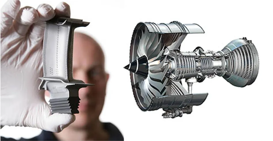
Turbine blades (e.g., Inconel 738) – exposed to hot combustion gases.
-
Combustor liners & flame tubes (e.g., Inconel 625) – endure cyclic thermal loads.
-
Nozzle guide vanes – require precision machining for aerodynamic efficiency.
However, machining Inconel presents significant challenges:
-
Rapid tool wear: The alloy’s hardness and abrasive microstructure shorten tool life.
-
Heat generation: Poor thermal conductivity leads to localized overheating.
-
Work hardening: Cutting forces can harden the material during machining.
-
Micro-cracking: Thermal stresses may cause defects in critical turbine components.
These challenges drive up production costs and require specialized techniques to ensure dimensional accuracy and surface integrity. This article explores why Inconel is so difficult to machine and provides actionable strategies to optimize the process for gas turbine applications.
2. Why Is Inconel Difficult to Machine?
Machining Inconel presents unique challenges due to its metallurgical properties and behavior under cutting forces. These difficulties are particularly pronounced in gas turbine components, where precision and material integrity are critical. Here are the key reasons why Inconel is notoriously difficult to machine:
1. High Strength at Elevated Temperatures
-
Inconel retains its strength even at temperatures exceeding 700°C (1,300°F), making it ideal for turbine blades and combustors.
-
However, this also means it resists deformation during machining, requiring higher cutting forces.
-
Work hardening: The material hardens rapidly when cut, leading to increased tool pressure and accelerated wear.
2. Abrasive Nature
-
The nickel-chromium matrix contains hard precipitates (e.g., gamma prime phase in Inconel 738), which act like sandpaper on cutting tools.
-
Compared to steel or aluminum, Inconel causes 3–5x faster tool wear, increasing production costs.
-
Common tool failures include chipping, flank wear, and cratering—especially in interrupted cuts (e.g., turbine blade cooling holes).
3. Heat Generation and Poor Thermal Conductivity
-
Inconel’s thermal conductivity is ~10 W/m·K (vs. 50+ for steel), so heat concentrates at the cutting edge instead of dissipating.
-
This leads to:
-
Thermal softening of tools (even carbide begins to degrade above 800°C).
-
Built-up edge (BUE), causing surface defects on finished parts.
-
4. Tendency to Crack and Residual Stresses
-
Micro-cracking: Localized heating and cooling during machining can induce micro-fractures, especially in thin-walled combustor liners.
-
Residual stresses: Uneven stress distribution may cause distortion post-machining, requiring additional stress-relief treatments.
Impact on Gas Turbine Components
-
Turbine Blades: Work hardening complicates precision profiling of airfoil shapes.
-
Combustors: Heat accumulation risks warping during drilling of cooling holes.
-
Nozzle Guide Vanes: Cracking risks demand conservative machining parameters.
Key Takeaway: Inconel’s properties that make it perfect for gas turbines also make it a nightmare to machine without optimized strategies.
3. Key Factors Affecting Inconel Machinability
Successfully machining Inconel for gas turbine components requires careful consideration of material grades, tooling, cutting parameters, and cooling methods. Here’s how to optimize each factor:
1. Material Grade Differences: Inconel 718 vs. 738 for Turbine Applications
-
Inconel 718:
-
Common Uses: Combustor casings, fasteners, shafts.
-
Machinability: Easier than 738 due to lower aluminum/titanium content.
-
Challenges: Still prone to work hardening; requires sharp tools.
-
-
Inconel 738:
-
Common Uses: Turbine blades (due to superior creep resistance at 900°C+).
-
Machinability: More difficult—higher gamma’ phase content increases abrasiveness.
-
Solution: Lower cutting speeds and specialized tool coatings.
-
| Property | Inconel 718 | Inconel 738 |
|---|---|---|
| Primary Use | Combustors, shafts | Turbine blades |
| Machinability | Moderate | Difficult |
| Key Challenge | Work hardening | Abrasive wear |
2. Tool Selection: Best Materials and Coatings
-
Tool Materials:
-
Carbide (Grade K or S): High wear resistance; best for roughing.
-
Ceramic (SiAlON): Withstands high temps; ideal for finishing.
-
CBN (Cubic Boron Nitride): For hardened Inconel (e.g., repaired blades).
-
-
Coatings:
-
TiAlN (Titanium Aluminum Nitride): Reduces heat-related wear.
-
AlCrN (Aluminum Chromium Nitride): Better for high-speed machining.
-
Example: A TiAlN-coated carbide end mill lasts 2–3x longer than uncoated tools when machining Inconel 718 combustor parts.
3. Cutting Parameters for Gas Turbine Parts
Optimal settings vary by operation (e.g., turning vs. milling) and component geometry:
| Operation | Speed (SFM) | Feed (IPR/IPT) | Depth of Cut (mm) |
|---|---|---|---|
| Rough Turning | 50–80 | 0.003–0.006 | 1.0–2.0 |
| Finish Milling | 30–60 | 0.001–0.003 | 0.1–0.3 |
| Drilling Holes | 20–40 | 0.002–0.004 | – |
Note: Turbine blade root machining often requires trochoidal milling to minimize tool engagement.
4. Cooling Strategies
-
High-Pressure Coolant (70–100 bar):
-
Flushes chips and reduces heat in critical zones (e.g., blade cooling holes).
-
-
Mist Cooling:
-
Effective for finish machining where fluid access is limited.
-
-
Cryogenic Cooling (LN2):
-
Emerging solution for suppressing work hardening.
-
Case Example: A turbine manufacturer reduced tool costs by 40% by switching to high-pressure coolant when machining Inconel 738 blade roots.
4. Practical Tips for Machining Inconel in Gas Turbine Components
To achieve high-quality Inconel parts for gas turbines, follow these proven strategies—from setup to post-processing.
1. Pre-Machining Preparation
A. Stress Relieving
-
Why? Inconel parts often retain residual stresses from forging or casting, which can cause distortion during machining.
-
Method: Heat treat at 650–750°C (1,200–1,380°F) for 1–2 hours before machining (critical for thin-walled combustor liners).
B. Workpiece Clamping
-
Challenge: Inconel’s high cutting forces can vibrate or displace the part.
-
Solutions:
-
Use hydraulic/pneumatic fixtures for turbine blades to avoid deformation.
-
Add soft jaws with serrated grips for combustor housings.
-
2. Toolpath Optimization
A. Trochoidal Milling for Blade Roots
-
Problem: Traditional milling causes excessive tool engagement and heat buildup in blade root slots.
-
Solution:
-
Trochoidal paths reduce tool load by maintaining constant chip thickness.
-
Parameters: 60–80 SFM, 0.002–0.004 IPT, stepover <30% of tool diameter.
-
B. Adaptive Clearing for Combustors
-
Avoid sharp directional changes in toolpaths to minimize heat concentration.
3. Post-Machining Treatments
A. Passivation
-
Purpose: Remove free iron particles and enhance corrosion resistance (critical for turbine parts exposed to exhaust gases).
-
Process: Immerse in 20–50% nitric acid at 20–60°C for 20–30 minutes.
B. Surface Finishing
-
Electropolishing: Smoothes internal passages of fuel nozzles to reduce turbulence.
-
Shot Peening: Induces compressive stress to improve fatigue life in turbine blades.
4. Case Study: Optimizing Inconel 718 Combustor Liner Machining
Problem: A manufacturer faced tool breakage every 3–4 parts and poor surface finish in combustor liner holes.
Solution:
-
Tool Upgrade: Switched to TiAlN-coated carbide drills with parabolic flutes.
-
Coolant Pressure: Increased to 80 bar through-tool coolant.
-
Parameters: Reduced speed to 35 SFM and feed to 0.002 IPR.
Results:
-
Tool life improved by 300% (12+ parts per tool).
-
Surface roughness (Ra) dropped from 3.2 µm to 0.8 µm.
Key Takeaways:
✔ Pre-machine stress relief prevents distortion in thin-walled parts.
✔ Trochoidal milling is ideal for blade roots and other high-load features.
✔ Passivation and electropolishing are essential for turbine part longevity.
5. Common Questions (FAQ) About Machining Inconel for Turbines
Q1: Is Inconel harder to machine than titanium or stainless steel?
A: Yes, Inconel is significantly more challenging due to:
-
Work hardening: Faster than titanium (Grade 5) or 316 stainless steel.
-
Tool wear: 3–5x higher than titanium under same conditions.
-
Heat resistance: Maintains strength at 700°C+, unlike steel (softens at 400°C).
Comparison Table:
| Material | Machinability Rating | Key Challenge |
|---|---|---|
| Inconel 718 | 15% (Very Poor) | Work hardening |
| Titanium 6Al-4V | 40% (Moderate) | Galling, heat buildup |
| Stainless 316 | 50% (Fair) | Built-up edge |
Q2: What is the best CNC machine for Inconel turbine blades?
A: Look for:
-
High rigidity: Box-way or linear guide machines (e.g., DMG MORI HSC 70).
-
Spindle power: ≥40 HP to handle cutting forces.
-
Coolant system: Through-spindle coolant (≥70 bar) for blade cooling holes.
-
5-axis capability: Essential for complex airfoil profiles.
Q3: How to reduce machining costs for Inconel gas turbine parts?
A: 5 Practical Strategies:
-
Tool life management: Use tool-presetting stations to maximize edge life.
-
Near-net-shape blanks: Reduce roughing time via precision casting/forging.
-
High-efficiency toolpaths: Trochoidal milling cuts cycle time by 20–30%.
-
Batch processing: Group small parts (e.g., turbine seals) for setup efficiency.
-
Alternative grades: For non-critical parts, consider Inconel 625 (better machinability than 718).
Q4: Can damaged Inconel turbine components be repaired by machining?
A: Yes, but with caveats:
-
Cracked blades: Requires laser cladding + re-machining (must restore airfoil geometry).
-
Worn seals: Can be machined oversize and paired with custom shims.
-
Combustor liners: Weld repair followed by stress relief and finish machining.
Note: Repaired parts often require requalification (e.g., FPI inspection).
6. Conclusion
Key Challenges & Solutions Recap
-
Problem: Inconel’s work hardening and heat resistance.
Fix: Optimized toolpaths, TiAlN-coated tools, and high-pressure coolant. -
Problem: Turbine blade distortion.
Fix: Stress relief pre-machining and trochoidal milling. -
Problem: High tooling costs.
Fix: Adaptive toolpaths and batch processing.
Why It Matters for Gas Turbines
Proper Inconel machining ensures:
✔ Longer component life (reduced micro-cracking).
✔ Higher engine efficiency (precision airfoils improve airflow).
✔ Lower maintenance costs (fewer unplanned shutdowns).
Need Expert Inconel Machining?
We specialize in high-tolerance Inconel parts for gas turbines, from blades to combustors. [Contact us] for a free DFM review to optimize your next project.
Get Quote
- Visit our website: https://www.nbyichou.com/
- Email us: [email protected]
- Call us/whatsapp: +86 13355741031
- Chat with us: Live chat support available on our website