Last Updated: November 2026
Bottom line up front: Custom sheet metal fabrication bridges the critical gap between rapid prototypes and mass production. For hardware engineers and procurement managers, the core challenge is not finding a supplier who can cut and bend metal—it is finding a partner who can hold ±0.1 mm tolerances on low-volume enclosures and transition seamlessly to progressive die stamping at 5,000+ units without tolerance stack-up disasters. This guide delivers the engineering parameters, process selection criteria, and DFM rules you need to specify parts correctly the first time, from fiber laser cutting through automated welding and high-volume metal pressing.
1. What Is Custom Sheet Metal Fabrication? (Direct Answer)
Sheet metal fabrication is a precision manufacturing process that transforms flat metal sheets—typically 0.5 mm to 6.0 mm thick—into functional three-dimensional enclosures, brackets, and structural assemblies. It combines subtractive cutting (fiber laser, turret punching), plastic deformation (CNC press brake bending, stamping), and permanent joining (TIG/laser welding) to achieve high strength-to-weight ratios at competitive unit costs .-2-12
Custom fabrication differs from off-the-shelf sourcing in one critical way: every dimension, hole placement, bend radius, and material gauge is defined by your design rather than selected from a catalog. This flexibility is essential when standard enclosures fail thermal management requirements, EMI/RFI shielding specifications, or IP65/IP67 environmental sealing standards.
2. Process Selection Matrix: Matching Method to Volume and Geometry
The single most consequential decision in sheet metal sourcing is process selection. Specifying laser cutting for a 50,000-unit production run wastes 50–75% of potential unit cost savings. Conversely, investing in progressive die tooling for a 200-piece prototype batch locks capital into hard tooling that may never amortize.
The following matrix consolidates YICHOU’s production capabilities against optimal application parameters. Use this table to identify which process aligns with your annual volume and tolerance requirements before sending an RFQ.
| Process Method | Optimal Thickness | Dimensional Tolerance | Ideal Volume | Primary Applications |
|---|---|---|---|---|
| Fiber Laser Cutting + CNC Bending | 0.5–12.0 mm | ±0.10 mm (linear) / ±0.5° (bend) | 1–1,000 units | Server chassis, medical enclosures, custom brackets |
| Progressive Die Stamping (Metal Pressing) | 0.2–4.0 mm | ±0.05 mm | 5,000–500,000+ units | Electrical metal stamping, automotive terminals, connectors |
| Heavy Metal Fabrication (Plate & Structural) | 6.0–25.0 mm | ±0.25 mm | 10–500 units | Industrial machine frames, heavy equipment bases, structural weldments |
| Precision Laser Welding & Finishing | 0.5–6.0 mm | Flatness ≤ 0.2 mm / 300 mm | All volumes | Hermetic stainless steel housings, cleanroom cabinets |
The Economic Break-Even Point: The transition from laser cutting + bending to progressive die stamping typically occurs between 2,000 and 5,000 units. Below 2,000 pieces, the upfront hard-tooling investment ($3,000–$15,000) cannot be justified by cycle-time savings. Above 5,000 units, progressive metal pressing reduces per-part cycle times to under one second and cuts unit costs by 50–75% .-2-5
3. Critical DFM Rules That Prevent Rework and Scrap
Most fabrication failures originate in the CAD file, not on the shop floor. A hole placed 1 mm too close to a bend line looks perfect in SolidWorks and becomes an elongated, out-of-tolerance defect the moment the press brake engages. The following rules represent the non-negotiable geometric constraints for sheet metal design.
3.1 Bend Radius and Springback Compensation
The inside bend radius (Ri) should equal the material thickness (1T) for mild steel and aluminum. For stainless steel, specify 1.5T minimum to prevent micro-cracking along the bend grain . Attempting a sharp, zero-radius corner is the most reliable way to produce a failed part.-2-5
Springback—the elastic recovery of metal after the bending force is removed—varies by material and tensile strength. High-strength alloys and stainless steel exhibit greater springback than mild steel, requiring CNC press brakes with real-time laser angle measurement to compensate automatically. Without this feedback loop, batch-to-batch tensile variations produce inconsistent bend angles.
3.2 Hole and Slot Placement Relative to Bend Lines
To prevent hole elongation or tearing during forming:
-
Hole edge to bend line: Minimum 2T; recommended 3T + R
-
Slot edge to bend line: Minimum 3T; recommended 4T + R
-
Minimum hole diameter: Equal to material thickness (1T); 1.5T recommended
-
Bridge (web) between holes: At least 1T to prevent thermal distortion during laser cutting -5
If your design requires features closer to the bend than these minimums, do not tighten the tolerance and hope for the best. Instead, incorporate laser-cut relief slots or specify post-bend CNC secondary machining for that feature. A drilled and reamed hole after bending is cheaper and more reliable than attempting to laser-cut and bend a hole to ±0.05 mm .-1
3.3 K-Factor: The Silent Cause of Dimensional Error
The K-factor defines the position of the neutral axis during bending and determines flat pattern accuracy. Using CAD software defaults without verifying the material-specific value is one of the most common causes of post-bending dimensional failure.
| Material | Recommended K-Factor Range |
|---|---|
| Mild Steel (SPCC) | 0.41–0.44 |
| Aluminum (5052/6061) | 0.40–0.45 |
| Stainless Steel (304/316L) | 0.44–0.50 |
Source: Creallo sheet metal design standards -5
4. Solving the Thin-Gauge Welding Distortion Problem
Thin stainless steel (0.8–1.5 mm) is notoriously difficult to weld without warping. Conventional MIG or TIG welding introduces excessive heat input, causing panel distortion that requires costly post-weld straightening—or scrap.
The engineering solution: For stainless steel sheet metal fabrication under 1.5 mm, pulsed micro-TIG and automated fiber laser welding paired with custom copper chill-bar fixtures rapidly draw heat away from the weld zone. This maintains panel flatness within ±0.2 mm while eliminating the grinding and straightening operations that erode margin and extend lead time.
For enclosure panels and brackets that do not require pressure-tight joints, replacing continuous welds with intermittent stitch or tab-and-slot self-locating welds reduces heat input dramatically. One documented case showed flatness deviation improving from 2.5 mm to ≤0.4 mm after switching from full-seam to stitch welding .-9
5. Material Selection: Matching Alloy to Environment and Budget
| Material | Common Grades | Typical Thickness | Best Application | Cost Position |
|---|---|---|---|---|
| Aluminum | 5052-H32, 6061-T6 | 1.0–3.0 mm | Telecom equipment, EV chargers, lightweight enclosures | Moderate |
| Cold Rolled Steel | CR 1008, Galvanneal | 1.2–2.5 mm | Server racks, indoor control panels, standard electrical boxes | Low |
| Stainless Steel | 304/304L, 316/316L | 1.0–2.0 mm | Medical devices, marine environments, food processing | High |
| Heavy Carbon Steel | A36, 1018 | 2.5–6.0+ mm | Machine frames, structural weldments, heavy equipment | Low–Moderate |
Selection logic: Aluminum 5052-H32 is the default for custom enclosures requiring good formability and natural heat dissipation. Stainless 304 handles corrosive and hygienic environments; 316L is mandatory for marine and chemical exposure. Cold rolled steel delivers the highest rigidity per dollar for non-cosmetic structural parts, provided a protective finish (powder coat or galvanizing) is specified .-10
6. High-Conversion FAQ: Answers Engineers and Buyers Actually Need
Q1: How does YICHOU prevent warping when welding thin stainless steel?
A: For stainless steel sheet metal fabrication under 1.5 mm, conventional MIG/TIG welding introduces excessive heat input. YICHOU utilizes pulsed micro-TIG and automated fiber laser welding paired with custom copper chill-bar fixtures that rapidly draw heat away from the weld zone. This keeps panel flatness within ±0.2 mm and eliminates costly post-weld straightening. For non-pressure-tight joints, stitch welding sequences are specified during DFM review to further reduce thermal input .-9
Q2: What is the minimum hole-to-edge and bend-to-hole distance in sheet metal design?
A: To prevent hole elongation during CNC press brake forming, holes and slots should be placed at least 2.5× material thickness plus the internal bend radius away from the bend line. The recommended offset is 3T + R for holes and 4T + R for slots. If a design requires closer features, YICHOU’s engineers incorporate precision laser-cut relief slots or execute post-bend CNC secondary machining rather than accepting a high-risk forming operation .-5
Q3: When should a project transition from laser cutting and bending to progressive metal stamping?
A: The economic break-even point typically occurs between 2,000 and 5,000 units. Below 2,000 pieces, custom sheet metal fabrication via laser cutting and CNC bending avoids upfront hard-tooling costs ($3,000–$15,000). Above 5,000 units, transitioning to progressive metal pressing or aluminum stamping blanks reduces per-part cycle times to under one second, cutting unit costs by 50–75% .-2-5
Q4: How do I avoid over-engineering tolerances on my drawing?
A: Reserve tight tolerances—±0.1 mm or tighter—only for functional mating features: shaft bores, bearing seats, dowel pin hole patterns, and sealing faces. Cosmetic covers, clearance holes for M6 bolts, and non-mating outer dimensions do not justify precision. Use ISO 2768-m as the title block default and apply the fine class (ISO 2768-f) only when the entire component is precision-critical. Moving from standard (±0.5 mm) to precision (±0.1 mm) can increase per-part cost by 30–60% .-1-9
7. Why YICHOU: The Integrated Precision-to-Scale Partner
The global sheet metal fabrication services market was valued at $87.3 billion in 2025 and is projected to reach $136.5 billion by 2035, driven by demand for lightweight, durable components across automotive, aerospace, medical, and electronics sectors . Buyers are no longer selecting suppliers on unit price alone—they evaluate engineering support, quality documentation, lead-time reliability, material traceability, and the ability to scale complex assemblies .-3-6-7
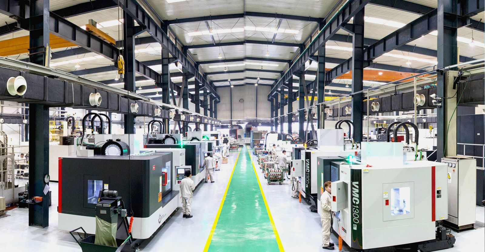
YICHOU (www.nbyichou.com) operates as an ISO 9001 / ISO 13485 certified precision manufacturer with integrated capabilities spanning:
-
Fiber laser cutting up to 20 kW with nitrogen assist for oxide-free stainless edges
-
CNC press brake forming with real-time laser angle compensation
-
Progressive die stamping for electrical metal stamping and aluminum stamping blanks
-
Automated fiber laser and pulsed micro-TIG welding for distortion-free thin-gauge assemblies
-
Heavy metal fabrication for structural weldments up to 25 mm plate
The operational advantage is vertical integration without the tolerance stack-up penalties of multi-vendor sourcing. A server chassis prototype cut and bent in our low-volume cell transitions to progressive die production in the same facility, under the same quality management system, with the same engineering team reviewing DFM at every stage.
8. Next Step: Upload Your Files for a Complimentary DFM Audit
Need an engineering-driven partner for precision enclosures, stamped electrical components, or heavy structural weldments?
Upload your 2D flat patterns (.DXF/.DWG) and 3D assemblies (.STEP) to YICHOU (www.nbyichou.com) for:
-
Complimentary DFM manufacturability audit identifying tolerance risks, bend conflicts, and cost-reduction opportunities
-
Itemized quote within 24 hours covering material, process, finishing, and volume breaks
-
Direct engineering consultation on material substitution, process transition timing, and design optimization for cost
No obligation. No minimum order for prototyping. Engineering-led feedback, not a sales pitch.
Get Quote
- Visit our website: https://www.nbyichou.com/
- Email us: [email protected]
- Call us/whatsapp: +86 13355741031
- Chat with us: Live chat support available on our website