The Ultimate DFM Guide: Mastering Component Tolerances and Wall Thickness for Custom Industrial Quartz Ware
Introduction: The Unforgiving Nature of High-Purity Quartz
Designing high-purity quartz components for semiconductor wafer processing, photovoltaic cells, or high-temperature laboratory environments presents a unique paradox. On a CAD screen, the design looks flawless; it exhibits the high-performance characteristics engineers demand. However, translating that digital perfection into a physical reality is a different story.
High-purity quartz glass possesses extraordinary thermal, optical, and chemical properties, making it indispensable for advanced manufacturing. Yet, it is also notoriously brittle, unforgiving of design errors, and highly sensitive to manufacturing parameters. A seemingly minor engineering choice—such as a sharp internal corner or an overly tight tolerance on a non-critical dimension—can lead to micro-cracking, structural failure under thermal cycling, or skyrocketing production costs.
This is where Design for Manufacturability (DFM) becomes non-negotiable. Integrating DFM principles early in your New Product Introduction (NPI) stage bridges the gap between theoretical engineering and flawless physical execution. It ensures that your custom quartz component will be not only functional but also cost-effective, reliable, and manufacturable at scale.
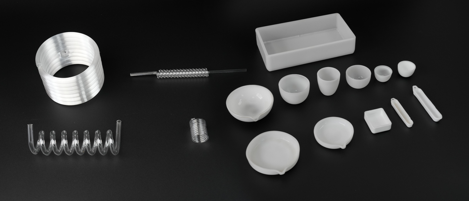
For engineers sourcing custom quartz glass parts or fused quartz components for diffusion furnaces, wet benches, or epitaxial reactors, understanding the golden rules of DFM is essential. Below is a comprehensive guide based on real-world fabrication practices, designed to help you optimize component tolerances and wall thickness for high-performance, high-purity applications.
Chapter 1: The Golden Rules of Quartz Glass DFM
Before diving into specific numbers, it is critical to understand the unique nature of quartz fabrication. Unlike metals that can be easily machined with standard tooling, quartz is a hard, brittle material that requires specialized processes. The fabrication route you choose—whether hot-working or cold-working—dramatically influences what is achievable, cost-effective, and reliable.
1.1 The Art of the Profile: Tolerances vs. Manufacturing Cost
In semiconductor applications, the gut reaction for many hardware engineers is to default to ultra-tight tolerances across the entire blueprint. This is a common DFM fallacy. With quartz glass, over-specifying tolerances is the fastest way to drive up scrap rates and machining times without adding functional value.
Unlike metals, quartz glass tolerances are highly dependent on whether the feature is hot-worked (flame-blown/lathe-formed) or cold-worked (CNC diamond-ground). Hot-working involves shaping quartz near its softening point using flame or lathe techniques. While this is essential for complex tubular assemblies and transitions, it inherently produces looser dimensional control due to the fluid nature of the process. Cold-working, on the other hand, employs precision CNC diamond grinding or ultrasonic machining on fully annealed, solid material. This yields significantly tighter tolerances but at a higher cost and longer cycle time.
Tightening a tolerance from ±0.2 mm to ±0.05 mm can triple the machining time because it requires slow, incremental passes with specialized diamond tooling to prevent micro-fractures. Each pass removes only microns of material, and the feed rates must be carefully controlled to avoid chipping. This means the machine spindle runs for hours instead of minutes, consuming machine capacity and driving up per-part cost.
Critical Dimensions vs. General Tolerances:
An experienced application engineer will always advise you to identify your critical dimensions first. A critical dimension is any feature that directly affects form, fit, or function—such as a sealing surface, an optical window flatness, a mating diameter for a flange connection, or a groove that holds an O-ring. Everything else should fall under a standard general tolerance.
Applying a precision tolerance to a non-critical hole depth or an outer diameter that never contacts another part adds zero value. It only increases inspection time, rejection risk, and manufacturing cost. The most cost-effective approach is to define a clear drawing with a general tolerance block (e.g., ±0.13 mm for linear dimensions) and then flag specific dimensions with tighter requirements where absolutely necessary.
Practical Tolerance Guidelines:
-
Linear Dimensions (Cold CNC Grinding): Standard ±0.13 mm is achievable on most geometries without excessive cost. Precision ±0.05 mm is possible but should be reserved for critical mating features. In special cases with ultra-precision equipment and optimal geometry, ±0.01 mm can be achieved, but this is exceptional and carries significant cost implications.
-
Wall Thickness (Tubing and Plates): Standard ±0.20 mm is typical for most structural requirements. If you need ±0.10 mm, expect longer machining times and more careful fixturing. Wall thickness is particularly sensitive because quartz tubes are often held in chucks during grinding, and any deflection can affect uniformity.
-
Hot-Worked or Flame-Formed Features: These generally fall into a ±0.50 mm standard range. Precision hot-working can achieve ±0.25 mm in some cases, but this requires highly skilled artisans and multiple setup steps. Features like bends, flares, and welded joints are inherently variable due to the manual or semi-automated nature of the process.
-
Surface Flatness (Per 25 mm Span): Standard flatness of 0.05 mm is adequate for most structural interfaces. Optical applications or vacuum sealing surfaces may demand 0.01 mm, which requires lapping or fine grinding steps after initial machining.
The Bottom Line on Tolerances:
Do not let pride or habit drive your tolerance specifications. Every micron of tightening adds cost, often exponentially. A part with a ±0.05 mm tolerance on every dimension may cost four to five times more than an identical part with ±0.13 mm on non-critical features. Work with your quartz fabricator early in the design phase to understand the cost-tolerance trade-off for your specific geometry.
1.2 Wall Thickness Consistency and Thermal Stress
Quartz ware frequently operates in environments exceeding 1000°C with rapid thermal cycles—sometimes ramping from ambient to 1100°C in under 30 minutes. While high-purity fused quartz has an exceptionally low coefficient of thermal expansion (approximately 5.5 × 10⁻⁷ per °C), severe transitions in wall thickness will still induce massive internal stress.
This phenomenon is often misunderstood. Because quartz expands so little with heat, many engineers assume that wall thickness variations are irrelevant. This is incorrect. The issue is not the absolute expansion of the material; it is the temperature gradient that develops across sections of differing thickness during transient heating or cooling.
When a thick quartz section meets a thin quartz wall, they absorb and dissipate heat at radically different rates. During a rapid temperature ramp, the thin wall quickly reaches the furnace temperature, while the thick section lags behind. This creates a temperature differential across the junction. Since the thin wall attempts to expand to its equilibrium size faster than the thick section can accommodate, localized strain develops. Similarly, during cooling, the thin section contracts faster, pulling against the still-hot thick region.
This localized thermal gradient causes structural stress concentration at the transition point. Over repeated thermal cycles, this stress accumulates and eventually triggers catastrophic cracking. In many cases, the crack initiates at the junction and propagates through the thin section or along the weld line.
Stress Concentration Mechanisms:
The severity of stress concentration depends on two factors: the magnitude of the wall thickness change and the abruptness of the transition. A sharp step from 2.0 mm to 4.0 mm creates a stress concentration factor that can be several times higher than a smoothly tapered transition. This is because the strain energy cannot distribute gradually; it accumulates at the sharp corner.
In addition to thermal stress, thicker sections also retain more residual stress from the manufacturing process. During CNC grinding or flame working, the surface layer of quartz experiences micro-cracking and localized heating. Thicker sections cool more slowly after processing, allowing more time for residual stresses to develop and become trapped within the bulk material. When combined with in-service thermal cycling, these residual stresses add to the operational stress, potentially exceeding the fracture toughness of the material.
Design Rules for Wall Thickness:
-
Uniformity is Paramount: Design parts with a consistent nominal wall thickness wherever possible. If you have a tube that needs a flange at the end, consider making the flange from a separate piece and welding it on, rather than machining a thick flange from a thick-walled tube. This allows each section to have an optimal thickness for its function.
-
For Tubular Components: For standard 50 mm diameter tubes operating at 1100–1200°C, a wall thickness of 1.5–2.5 mm provides an optimal balance. This range gives enough structural rigidity to support the tube's own weight and any process loads, while remaining thin enough to minimize thermal gradients. Thinner walls (1.0–1.5 mm) offer superior thermal shock resistance and can survive more aggressive cycling, but they are more fragile and prone to mechanical damage during handling.
-
For Larger Diameters: Tubes in the 75–100 mm diameter range often require an additional 12–18% wall thickness to maintain hoop strength and resist sagging at high temperatures. However, this increased thickness comes at the cost of higher thermal stress. In these cases, designers often specify a slightly thicker wall with a carefully controlled heating and cooling ramp rate to manage the stress.
-
Transition Design: If a thickness change is functionally mandatory—such as a reinforced mounting flange or a thickened sealing land—use a gradual taper rather than a sharp step-down. A taper ratio of 3:1 (three units of axial length for every one unit of thickness change) is highly recommended to distribute internal stress evenly. In critical applications, a 5:1 taper provides even better stress distribution but consumes more axial space.
-
Avoid Isolated Thick Sections: A thick boss or pad on an otherwise thin wall creates a "hot spot" that absorbs heat differently. If such features are unavoidable, consider making them from a separate piece that is welded on, or use a gradual radius to transition between thicknesses.
Thermal Cycling Considerations:
The number of thermal cycles your component will endure is a critical design input. A part that cycles once per day for five years (approximately 1,825 cycles) has very different stress requirements than a part that cycles once per hour (over 8,700 cycles per year). For high-cycle applications, wall thickness uniformity and generous transition radii become even more critical. Some semiconductor processes cycle multiple times per hour, subjecting quartz components to thousands of thermal shocks over their service life. In these environments, even minor thickness variations can drastically reduce component lifetime.
1.3 Eliminating Sharp Internal Corners (Radii vs. Sharp Cuts)
One of the most common DFM errors in custom quartz design is specifying sharp 90° internal corners on machined pockets, slots, or stepped bores. This mistake appears frequently on drawings from mechanical engineers who are accustomed to metals. In metal machining, sharp corners are difficult but often achievable with EDM or specialty tooling. In quartz, they are virtually impossible to produce without inducing damage.
Stress Concentration Effects:
From a mechanical standpoint, a sharp internal corner acts as a massive stress riser. The theoretical stress concentration factor for a sharp 90° corner approaches infinity. In practice, even a small radius significantly reduces this factor. A radius of just 0.5 mm can cut the stress concentration factor in half compared to a sharp corner. A radius of 1.5 mm reduces it to near-negligible levels for most geometries.
When a quartz component with sharp internal corners is subjected to thermal cycling or mechanical loading, the stress at the corner concentrates to several times the nominal stress in the surrounding material. If this concentrated stress exceeds the fracture toughness of quartz (approximately 0.7–1.0 MPa·√m), a crack initiates. Once a crack starts, it propagates rapidly through the brittle material, often leading to complete fracture within a few thermal cycles.
Manufacturing Reality:
From a manufacturing standpoint, creating a perfectly sharp internal corner via CNC milling is physically impossible. Rotating diamond-coated milling tools are cylindrical, and they naturally leave a radius equal to the radius of the tool. To create a sharp corner, the tool would need to have zero radius, which does not exist.
In practice, the minimum achievable internal radius is equal to the radius of the cutting tool. For typical CNC grinding of quartz, tools range from 1.0 mm to 6.0 mm in diameter. A 3.0 mm diameter end mill (1.5 mm radius) is common for general-purpose machining. If you specify a sharp 90° corner, the fabricator will have to use a smaller tool to get closer to the corner, then potentially use multiple passes or EDM techniques to reduce the radius. Each of these steps adds cost, cycle time, and risk of tool breakage or workpiece chipping.
Design Guidelines for Internal Radii:
-
Add Fillets to All Internal Corners: Always design internal corners with a generous radius (fillet). This applies to pockets, slots, stepped holes, and any other cavity.
-
Minimum Radius Rule of Thumb: Ensure the internal radius is at least 10–15% larger than the radius of the cutting tool you expect to be used. If you do not know the tool size, a conservative rule is to make the internal radius at least 1.5 mm for any pocket deeper than 5 mm. For deeper pockets, the radius should increase proportionally.
-
Depth-to-Radius Relationship: If a pocket is 10 mm deep, a minimum internal corner radius of 1.5 mm allows the CNC machine to clear the material smoothly without stalling or chipping the quartz. A radius of 2.0 mm is even better. For pockets deeper than 20 mm, consider a radius of 3.0 mm or more, as longer tools require larger radii to maintain rigidity and avoid deflection.
-
External Corners: While internal corners are the primary concern, external corners also benefit from radii. A chamfer or radius on an external edge reduces chipping risk during handling and installation. It also makes the part less likely to chip if it is accidentally bumped against another surface.
-
Through-Holes and Slots: For through-holes, the bottom of the hole has a radius determined by the tool. If a flat bottom is required, a secondary operation is needed. For slots, the ends of the slot will have the tool radius. Ensure your slot length accounts for this.
Case Example:
Consider a quartz component with a rectangular pocket that is 20 mm wide, 30 mm long, and 10 mm deep. A drawing specifying sharp 90° corners is essentially unmachinable as drawn. The fabricator will contact you to request a radius. If you approve a 1.5 mm radius, the fabricator can use a 3.0 mm diameter tool and machine the pocket efficiently. If you insist on a 0.5 mm radius, the fabricator must use a 1.0 mm diameter tool, which is fragile and prone to breakage. The machining time increases by at least 50%, and the risk of scrap increases significantly. A 2.0 mm radius would allow a larger, more robust tool and even faster cycle times.
Chapter 2: The Physics of Quartz Machining
Understanding the material properties and the physics of machining is crucial for effective DFM. Quartz is not just "glass"; it is a hard, brittle material with unique characteristics that demand respect and understanding from the design engineer.
2.1 Diamond Grinding and the Brittle-Ductile Transition
Machining quartz requires diamond tooling. Conventional abrasive wheels—such as those made from corundum or silicon carbide—wear rapidly when cutting quartz and risk contaminating the workpiece with foreign particles. Diamond wheels, on the other hand, provide exceptional tool life and controlled chip formation. A well-maintained diamond wheel can machine quartz for hundreds of hours before requiring dressing, while conventional wheels may need replacement after just a few hours of cutting time.
The key to achieving crack-free surfaces in quartz machining lies in what materials scientists call ductile mode grinding. Under controlled conditions, it is possible to machine brittle materials like quartz so that material is removed by plastic flow rather than brittle fracture. In ductile mode, the quartz behaves almost like a metal, with chips shearing off in a continuous stream rather than shattering into dust.
This phenomenon occurs when the undeformed chip thickness—the thickness of the material being removed by each individual diamond grit—is kept below the ductile-brittle transition value. For quartz, this critical thickness is generally in the order of 0.1 micrometers (100 nanometers). This means the grinding wheel must have extremely fine grit size, the machine must have sub-micron positioning accuracy, and the feed rates must be carefully controlled.
The Engineering Implications:
Achieving ductile mode grinding requires machine system accuracy and dynamic stiffness between the grinding wheel and the workpiece. The machine must be rigid enough to resist deflection, the spindle must run with minimal runout, and the coolant must effectively flush away chips to prevent re-cutting. This is why fabricators investing in high-stiffness, ultra-precision CNC grinding machines can hold tolerances far tighter than those using standard equipment.
For the design engineer, this means understanding that not all fabricators can achieve the same tolerance capability. When specifying tight tolerances, you must ensure your chosen fabricator has the appropriate equipment and process controls. Low-cost fabricators using older or lower-rigidity machines may struggle to hold ±0.05 mm consistently, especially on complex geometries.
Surface Finish Considerations:
Ductile mode grinding produces surfaces with a mirror-like finish, with roughness (Ra) values below 0.1 micrometers. Brittle mode grinding, on the other hand, produces a frosted or matte surface with micro-cracks. These micro-cracks are invisible to the naked eye but significantly reduce the strength of the component. A part machined entirely in brittle mode may have only 30–50% of the theoretical strength of a part machined in ductile mode.
For most semiconductor applications, a surface finish of 0.4–0.8 micrometers Ra is acceptable for structural parts. Optical components and sealing surfaces require 0.1 micrometers Ra or better, which demands ductile mode grinding and subsequent polishing or lapping.
2.2 Cycle Life and Thermal Performance
The wall thickness of your quartz component directly impacts its cycle life and overall performance. This relationship is not linear; there are distinct regimes where performance changes dramatically.
Thin-Wall Components (1.0–1.5 mm):
These components excel in applications with extreme thermal cycling. The low thermal mass and uniform heat distribution allow them to ramp from ambient to process temperature and back with minimal stress. Data from controlled testing shows that thin-walled tubes can survive over 2,100 thermal cycles at a 5°C/min ramp rate before showing signs of degradation. The measured thermal stress in these components is typically 15–25 MPa, well below the fracture threshold.
However, thin walls are mechanically fragile. They require careful handling during installation and are more susceptible to damage from process upsets, such as sudden pressure changes or mechanical vibrations. They are also more prone to sagging at very high temperatures (above 1250°C) where the quartz begins to soften.
Standard-Wall Components (1.5–2.5 mm):
This is the "sweet spot" for most general-purpose semiconductor and laboratory quartz ware. For a 50 mm diameter tube, a 1.8–2.3 mm wall provides an optimal balance of thermal performance and mechanical robustness. These components survive 1,000 thermal cycles with a 95% survival rate, keeping stress below the 50 MPa failure threshold.
Standard-wall tubes can handle typical wafer processing temperatures (1000–1150°C) without sagging, are robust enough for moderate handling, and can accommodate common process conditions. The cost to manufacture is moderate because the wall thickness is within the capability of standard tube drawing and CNC grinding processes.
Thick-Wall Components (3.0–5.0 mm):
These components are necessary for large-diameter tubes (75–100 mm) or applications requiring high hoop strength and resistance to external pressure. The thicker wall manages higher temperature gradients and provides greater structural rigidity. However, the thicker wall comes with significant thermal stress penalties.
At a wall thickness of 3.5 mm, thermal stress during a standard 5°C/min ramp exceeds 55 MPa, dangerously close to the fracture threshold for many geometries. To safely use thick-wall components, the process engineer must often reduce the heating and cooling ramp rates, sacrificing throughput for component life. This trade-off must be carefully evaluated during the design phase.
Thickness Selection Guidelines:
| Wall Category | Thickness Range (mm) | Best Application | Thermal Stress Level | Cycle Life Expectation |
|---|---|---|---|---|
| Ultra-Thin | 0.8 – 1.2 | Extreme rapid cycling, small diameters | Very low (15–20 MPa) | 2,000+ cycles |
| Thin | 1.0 – 1.5 | High-cycle applications, aggressive ramps | Low (20–30 MPa) | 1,500–2,000 cycles |
| Standard | 1.5 – 2.5 | General furnace tubes, diffusion processes | Moderate (30–45 MPa) | 800–1,200 cycles |
| Medium | 2.5 – 3.5 | Larger diameter tubes, moderate pressures | Moderate-High (45–55 MPa) | 400–800 cycles |
| Thick | 3.5 – 5.0 | High-pressure, large diameter, structural supports | High (55–70 MPa) | 200–400 cycles |
| Ultra-Thick | 5.0+ | Specialized pressure vessels, unique applications | Very High (70+ MPa) | <200 cycles (requires slow ramps) |
The Thermal Stress Equation:
For those who want a more quantitative approach, thermal stress in a quartz tube wall can be estimated using the following relationship:
σ_thermal ∝ (E × α × ΔT) / (1 – ν)
Where:
-
E is the elastic modulus of quartz (~72 GPa at room temperature, decreasing at elevated temperatures)
-
α is the coefficient of thermal expansion (~5.5 × 10⁻⁷ per °C)
-
ΔT is the temperature difference between the inner and outer wall during transient conditions
-
ν is Poisson's ratio (~0.17 for quartz)
The key insight is that ΔT is directly proportional to the square of the wall thickness for a given heat flux. Therefore, doubling the wall thickness quadruples the thermal stress. This is why thin walls are so much more thermally forgiving.
Chapter 3: Prototyping vs. Series Production
Navigating the transition from a prototype to a finalized production run shouldn't mean facing massive financial barriers. In the semiconductor R&D and laboratory sectors, engineers frequently need to validate a design with a small test batch of 5 to 10 pieces before committing to capital-intensive infrastructure or high-volume production contracts.
3.1 The Prototyping Advantage
This is where agile, low-volume quartz manufacturing excels. Utilizing state-of-the-art multi-axis CNC diamond grinding and specialized ultrasonic machining, parts can be produced directly from CAD data without the need for expensive hard tooling. This represents a significant departure from traditional manufacturing models that required significant upfront investment in custom molds, dies, or fixtures.
Eliminating MOQ Barriers:
One of the most significant advantages of modern quartz fabrication is the elimination of restrictive Minimum Order Quantities (MOQs). Many advanced quartz fabricators are structured specifically to support the NPI timeline. They understand that semiconductor R&D and university laboratories often need just one or two pieces for feasibility testing, process development, or equipment retrofitting.
You can order a single prototype without surcharges or extended lead times. This "zero-MOQ" capability allows you to validate form, fit, and function before committing to a larger production run. It also enables rapid iteration; if the prototype reveals a design flaw, you can update the CAD file and order a second prototype within days, not weeks or months.
Speed to Market:
In the semiconductor industry, time-to-market is everything. A delay of a few weeks in receiving a critical quartz component can delay an entire process development project, costing millions in lost revenue. Prototyping with low-volume manufacturing streamlines the NPI timeline by eliminating the lengthy tooling development phase that traditional manufacturing methods require.
Cost-Effective Validation:
For many engineering teams, the cost of a few prototypes is trivial compared to the cost of a production run of flawed parts. If you order 500 pieces of a component with a design flaw, you have 500 scrap parts and a significant financial loss. If you order five prototypes first, discover the flaw, and correct it, your total loss is limited to the cost of those five parts. This is a fundamental principle of DFM and NPI: test early, test often, and test with actual production-grade manufacturing processes.
3.2 Scaling to Production
Once the prototype has been validated, scaling to larger production volumes is straightforward. The same CNC programs, fixturing strategies, and quality control protocols developed during the prototyping phase transfer directly to production. There is no need to re-engineer the part or develop new tooling.
This seamless transition from prototype to production is one of the key advantages of modern CNC-based quartz fabrication. It minimizes the risk of introducing new variables during scale-up and ensures that the production parts are identical to the validated prototypes.
Process Optimization for Volume:
As volumes increase, fabricators can optimize the process for efficiency. This may involve:
-
Using larger batch sizes in the furnace annealing step
-
Employing multi-part fixturing to machine multiple components simultaneously
-
Reducing cycle times by optimizing feed rates and tool paths
-
Implementing automated inspection systems for faster quality control
These optimizations reduce per-part cost as volume increases, making the transition from prototype to production economically attractive.
Quality Consistency:
One of the often-overlooked benefits of starting with a robust CNC-based prototyping process is the consistency it provides. CNC programs are repeatable; once the program is proven, every part produced from that program will be nearly identical. This reduces variability and improves yield, which is particularly important in high-volume production where even a small scrap rate can have significant financial impact.
Chapter 4: Advanced Design Considerations
Beyond the fundamentals of tolerances, wall thickness, and internal radii, there are several advanced design considerations that can significantly improve the performance and manufacturability of custom quartz components.
4.1 Annealing and Residual Stress
Quartz components can develop significant residual stress during manufacturing. Grinding, cutting, and flame-working all introduce localized heating and mechanical deformation that can leave the material in a state of high internal stress. If these stresses are not relieved before the component is put into service, they can combine with operational stresses and cause premature failure.
The Annealing Process:
Annealing involves heating the quartz component to a temperature near its softening point (typically 1050–1150°C) and holding it at that temperature for a specific period. This allows the molecular structure to relax, eliminating internal stress. The component is then cooled very slowly—often over 12–24 hours—to prevent new stress from developing during cooling.
DFM Implications:
For the design engineer, the primary implication is that complex or heavily machined parts require longer annealing cycles. A simple tube with minimal machining may anneal in 6–8 hours, while a complex assembly with multiple welded joints and heavy machining may require 24–36 hours. This adds to lead time and cost.
Annealing also affects dimensional stability. During annealing, the quartz undergoes slight shrinkage as the molecular structure relaxes. For parts with extremely tight tolerances, it is often necessary to grind the part to a slightly oversize dimension, anneal it, and then perform a final finish grinding pass to achieve the final dimension. This two-step process adds cost but ensures that the part maintains its tolerance after the stress-relief cycle.
4.2 Welding and Joining
Many custom quartz components require welding to join multiple pieces—such as attaching flanges to tubes, connecting tubes of different diameters, or installing viewports. Quartz welding is a specialized skill that requires precise flame control and a deep understanding of quartz behavior at high temperatures.
Weld Design Principles:
-
Overlap Length: Weld joints should have sufficient overlap to ensure strength and gas-tightness. For a typical butt weld between two tubes of the same diameter, an overlap of at least 1.5 times the wall thickness is recommended.
-
Weld Penetration: The weld should fully penetrate the joint, with no voids or inclusions. Incomplete penetration creates stress risers and potential leak paths.
-
Heat-Affected Zone (HAZ): The region adjacent to the weld undergoes thermal cycling during the welding process. This can change the material's microstructure and create residual stress. The HAZ should be as narrow as possible, which requires precise heat control.
-
Post-Weld Annealing: Any welded assembly should be annealed after welding to relieve the stress introduced during the process. This is especially important for complex assemblies with multiple weld joints.
4.3 Surface Finish and Cleanliness
Quartz components for semiconductor applications must meet stringent cleanliness standards. Particles, contaminants, or micro-cracks on the surface can lead to process contamination, reduced yield, or component failure.
Surface Finish Requirements:
-
As-Machined: Typical CNC ground finish of 0.4–0.8 micrometers Ra is acceptable for many structural applications.
-
Polished: Optical components, sealing surfaces, and high-purity process areas often require a polished finish of 0.05–0.1 micrometers Ra. Polishing removes the micro-cracked layer left by grinding and creates a smooth, clean surface.
-
Flame-Polished: Some components are flame-polished to create a smooth, glossy surface without the need for mechanical polishing. This is common for complex shapes that are difficult to polish mechanically. However, flame polishing introduces new thermal stress and should be followed by annealing.
Cleaning and Packaging:
After final machining and annealing, quartz components are cleaned in a controlled environment to remove any residual particles or contaminants. This may involve ultrasonic cleaning, acid washing, or deionized water rinsing. The components are then packaged in cleanroom-grade materials to maintain cleanliness during shipping. Design engineers should specify cleanliness requirements on the drawing if they are critical to the application.
Conclusion: Stop Guessing, Start Optimizing
Don't wait until your design is locked down and sent to procurement to discover that it is either unmachinable or prohibitively expensive to produce. Designing high-purity quartz requires a careful balance of material science, thermal physics, and practical machining dynamics.
Key Takeaways to Implement Today:
-
Tolerance Strategy: Differentiate between critical and non-critical dimensions. Don't apply precision tolerances globally; it increases cost and lead time without improving function. Standard tolerances (±0.13 mm) are adequate for most features; reserve precision (±0.05 mm) for mating surfaces, seals, and optical areas.
-
Wall Thickness: Keep it uniform to avoid thermal stress. Use blended transitions with a 3:1 slope for any mandatory changes. For most 50 mm tubes, 1.5–2.5 mm thickness provides an optimal balance of thermal performance and structural integrity.
-
Internal Corners: Always add generous fillets (minimum 1.5 mm) to prevent stress risers and facilitate machining. Remember that the tool radius naturally limits the achievable internal radius.
-
Diamond Tooling: Recognize that fabricators rely on diamond tooling for quartz. Design features that play to the strengths of this process—such as generous radii and consistent wall thickness—rather than fighting against its limitations.
-
Prototype First: Take advantage of low-volume manufacturing to validate your design before scaling to high-volume production. The cost of a few prototypes is trivial compared to the cost of a flawed production run.
-
Annealing and Stress Relief: Ensure that complex or heavily machined parts are properly annealed to relieve residual stress. Understand that annealing adds time and cost but is essential for reliability.
-
Cleanliness Specifications: Clearly specify any cleanliness requirements on the drawing. Differentiate between structural, optical, and high-purity surfaces.
-
Partner Early: Engage your quartz fabricator during the design phase, not after the design is locked. An experienced application engineer can provide valuable guidance on manufacturability, cost reduction, and reliability improvement.
At our advanced manufacturing facility, we specialize in turning complex engineering concepts into flawless, high-value-added quartz realities. By partnering with us early in your design phase, you leverage decades of fabrication expertise to optimize your components for performance and manufacturability. We offer everything from single-piece prototypes to high-volume production runs, with the flexibility to meet your NPI timeline and quality requirements.
Frequently Asked Questions (FAQ)
Q1: What are the typical machining tolerances for CNC ground quartz parts?
Standard CNC grinding tolerances for quartz are typically ±0.13 mm for linear dimensions and ±0.20 mm for wall thickness. Precision applications can achieve ±0.05 mm for linear dimensions, but this is reserved for critical mating surfaces and sealing areas. Tolerances tighter than ±0.05 mm are possible with specialized equipment but carry significant cost and lead-time implications.
Q2: How does wall thickness affect thermal shock resistance?
Thermal stress increases with the square of the wall thickness. Therefore, thinner walls (1.0–1.5 mm) offer superior thermal shock resistance, allowing for more aggressive heating and cooling cycles with lower internal stress. Thicker walls (3.0 mm and above) require slower ramp rates to avoid cracking. For most standard furnace applications, a 1.5–2.5 mm wall provides a good balance of thermal performance and mechanical robustness.
Q3: Why are sharp internal corners bad for quartz design?
Sharp internal corners act as stress risers and are nearly impossible to create perfectly with CNC diamond milling tools. The theoretical stress concentration factor at a sharp 90° corner approaches infinity, making it a likely initiation point for cracks during thermal cycling or mechanical loading. Adding a fillet radius of at least 1.5 mm significantly reduces stress concentration and makes the part manufacturable.
Q4: What is the difference between hot-working and cold-working tolerances?
Hot-working (flame forming) involves shaping quartz near its softening point and results in looser tolerances (±0.50 mm typical) due to the fluid nature of the process. Cold-working (CNC grinding) uses precision diamond tooling on fully annealed material and allows much tighter tolerances (±0.13 mm standard, ±0.05 mm precision). Hot-working is used for complex assemblies, bends, and transitions; cold-working is used for precision features and flat surfaces.
Q5: Is it difficult to get small quantities of custom quartz parts?
No. Many specialized quartz fabricators offer low-volume prototyping with zero-MOQ (minimum order quantity) requirements. You can order as few as 1–5 units for testing and validation without requiring expensive tooling or committing to large production volumes. This is ideal for semiconductor R&D, university research, and process development where flexibility is critical.
Q6: What is annealing and why is it important?
Annealing is a heat treatment process that relieves internal stresses introduced during machining, grinding, and welding. The component is heated to approximately 1050–1150°C, held at temperature to allow stress relaxation, and then cooled very slowly. Proper annealing is essential for reliability, especially for complex components that experience thermal cycling in service. Without annealing, residual stresses can combine with operational stresses and cause premature failure.
Q7: How should I specify surface finish on my quartz drawing?
Surface finish should be specified using Ra (average roughness) values. For structural parts, Ra 0.4–0.8 micrometers is typical. For optical components and sealing surfaces, Ra 0.05–0.1 micrometers is required. If cleanliness is critical (e.g., for semiconductor process chambers), specify a cleanroom cleaning and packaging protocol. Always discuss surface finish requirements with your fabricator to ensure they are achievable and cost-effective.
Q8: What is the maximum operating temperature for fused quartz?
High-purity fused quartz can operate continuously at temperatures up to 1150°C and intermittently up to 1200°C. Above these temperatures, the quartz begins to soften and deform under its own weight. The specific temperature limit depends on the application, loading conditions, and required service life. For extended service above 1100°C, consider using a material with higher temperature capability, such as opaque quartz or ceramic.
Q9: Can I machine quartz on standard CNC equipment?
Standard CNC equipment is not suitable for quartz machining. Quartz requires specialized CNC grinders with high-rigidity spindles, diamond tooling, and advanced coolant systems. Conventional machining methods used for metals (milling cutters, abrasive wheels) will cause severe chipping, cracking, and rapid tool wear. Always use a fabricator with dedicated quartz machining capabilities.
Q10: How do I choose between clear fused quartz and opaque quartz?
Clear fused quartz offers superior optical transparency, higher purity, and better thermal shock resistance. It is the standard choice for most semiconductor and laboratory applications. Opaque quartz (also called milky quartz or opaque fused silica) contains microscopic bubbles that scatter light. It is often used for furnace liners and insulation applications where optical clarity is not required and where lower cost is acceptable. Opaque quartz has slightly lower thermal shock resistance than clear fused quartz.
For more detailed technical discussions or to discuss your specific quartz component requirements, contact our engineering team today. We are ready to help you optimize your design for manufacturability, performance, and cost-effectiveness.
Contact us today for a competitive quote and technical support!
Let Yichou help you achieve excellence in your next project. Whether you need raw materials, custom solutions, or precision-manufactured components, our team is ready to assist.
- Email us: [email protected]
- Call us/whatsapp: +86 13355741031
- Chat with us: Live chat support available on our website