Form Follows Aerodynamics: Overcoming Geometric Complexity in 5-Axis Machined Blisks and Turbine Vanes
In aerospace and power generation, "mission-critical" is not a marketing buzzword—it is an engineering boundary. Components inside modern jet engines and high-efficiency gas turbines withstand extreme thermal stresses that often exceed the melting point of the metal itself, combined with immense centrifugal forces at high rotational speeds.
Under these operating conditions, a single micro-fracture or structural imperfection can trigger uncontained engine failure. The margin for error is absolute zero. This reality defines the relationship between design engineers and their manufacturing partners.
For international aerospace procurement managers, sourcing manufacturers capable of delivering next-generation aerodynamics requires moving beyond standard machine shops. It demands specialized capabilities in custom 5-axis CNC machining for complex aerospace components and advanced Inconel 718 CNC milling. The distinction between a generalist shop and one that truly understands propulsion component manufacturing is visible in every aspect of their operation—from machine tool selection to quality documentation and supply chain transparency.
In this comprehensive guide, we explore how cutting-edge multi-axis machining and advanced metallurgy converge to conquer the most challenging components in aerospace propulsion. We also examine what procurement teams must verify when qualifying suppliers for these demanding programs, and how to make data-driven sourcing decisions that minimize supply chain risk.
Part 1: The Art of 5-Axis Continuous Milling for Blisks and Impellers
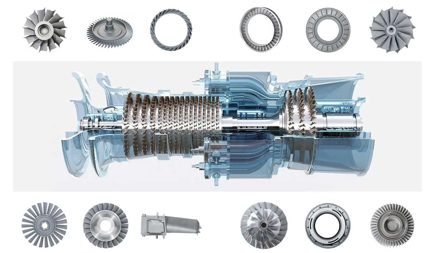
Among all propulsion components, the integrally bladed rotor—commonly known as a blisk—and its associated precision machined turbine blades and vanes represent the pinnacle of geometric complexity. Historically, compressor rotors were assembled by slotting individual blades into a central disk. Today's high-efficiency engines demand monolithic components where the disk and blades are machined from a single, solid forging.
This design evolution is driven by pure physics. A monolithic blisk eliminates the mechanical joints between blades and disk, reducing weight while improving structural integrity and aerodynamic efficiency. However, this performance gain comes at a significant manufacturing cost that only elite suppliers can absorb.
The 5-Axis Mandate: Why 3-Axis and 4-Axis Machining Cannot Deliver
Traditional 3-axis or 4-axis machining setups simply cannot manufacture a modern blisk or complex impeller. The cutting tool approaches from a fixed orientation, making it impossible to navigate the tight, curved channels between blades without colliding with the workpiece. Only simultaneous 5-axis continuous milling allows the tool to follow the complex contours while maintaining proper clearance.
The twisted, overlapping, and non-developable aerofoil surfaces mean that the cutting tool must continuously adjust its orientation to avoid colliding with adjacent blades. This requires machine kinematics that support full contouring capability across all five axes simultaneously—not just positional 3+2 machining.
text
[Solid Forged Superalloy Disc] ➔ [Simultaneous 5-Axis Adaptive Roughing] ➔ [Point-Contact Finishing Pass] ➔ [Monolithic Blisk]
Advanced CAM Programming: The Intelligence Behind the Cut
To achieve smooth, aerodynamic surfaces without sub-surface damage, elite manufacturers rely on advanced CAM programming:
Optimized Tool Entry Angles: Advanced CAM software calculates exact tool-to-part engagement to prevent tool deflection and eliminate localized surface scallops. The software must account for the dramatic changes in tool axis vector that occur when machining leading and trailing edges. Modern CAM systems use multi-axis collision avoidance algorithms that automatically adjust tilt angles to maintain safe clearance while maximizing material removal rates.
Vibration Control and Chatter Elimination: By maintaining a constant chip load through specialized barrel cutters and point-contact finishing passes, the machine eliminates micro-chatter, ensuring a flawless surface profile right off the machine. Feedrate scheduling is particularly critical in regions with very small radii of curvature, where conventional scheduling can cause flutter and reduced accuracy.
Tool Path Strategies for Blisk Machining:
| Machining Stage | Primary Strategy | Key Objective |
|---|---|---|
| Adaptive Roughing | Trochoidal milling with high radial engagement | Maximize material removal while minimizing tool wear |
| Semi-Finishing | Constant scallop height tool paths | Prepare uniform stock for finishing |
| Finishing | Point-contact with barrel cutters | Achieve < 0.0004" profile accuracy |
| Clean-up | Specialized lollipop cutters | Remove remaining material in tight fillet areas |
The machining of a single blisk can require 8 to 24 hours of cutting time per blade, with some large blisks featuring 36 or more blades. The roughing stage alone demands careful tool selection and path planning to remove the bulk of material efficiently, followed by semi-finish and finish stages that progressively refine the surface to final specifications.
Key Insight: A supplier's CAM programming capability is often the strongest indicator of their ability to handle complex blisk geometries. During supplier qualification, procurement teams should request sample tool paths and verify that the CAM post-processor is validated for the specific machine tool being used.
Part 2: Taming Superalloys—Titanium Grade 5 and Inconel 718
Aerospace propulsion engineers face a unique metallurgy paradox: the exact material properties that allow a part to survive inside a blazing gas turbine also make it incredibly difficult to cut. Materials like Titanium Grade 5 (Ti-6Al-4V) and Inconel 718 are notoriously brutal on cutting tools and demand an entirely different machining approach than standard metals.
Understanding how to machine Inconel 718 and Titanium for mission-critical parts requires specialized processing strategies to overcome their native material properties. These alloys are grouped under "difficult-to-cut materials," but treating them as interchangeable is a fundamental mistake that leads to catastrophic tool failure and scrapped parts.
Inconel 718: Conquering Work Hardening and Abrasive Wear
Inconel 718 is a nickel-based superalloy that retains its mechanical strength at temperatures exceeding 1,300°F. Its austenitic crystalline structure resists slip, meaning the material does not shear cleanly under a cutting edge.
The Critical Failure Mechanism: If a cutting tool rubs against the material rather than cleanly shearing it, the surface instantly work-hardens, becoming harder than the cutting edge itself. This results in rapid notch wear at the depth-of-cut line, followed by sudden and unpredictable tool failure.
Machining Inconel requires:
-
Rigid, heavy-duty spindles with high torque at low RPM
-
Aggressive positive-rake geometries optimized for nickel alloys
-
Constant, uninterrupted feed rates—hesitation is fatal
-
Ceramic or CBN (cubic boron nitride) inserts for roughing operations
-
Carbide substrates with advanced AlTiN or TiAlN coatings for finishing
Typical Machining Parameters for Inconel 718:
| Operation | Cutting Speed (SFM) | Feed Rate (IPR) | Depth of Cut (inches) | Tool Material |
|---|---|---|---|---|
| Rough Turning | 100-200 | 0.008-0.015 | 0.060-0.120 | Ceramic |
| Finish Turning | 250-350 | 0.004-0.008 | 0.010-0.030 | Carbide-AlTiN |
| Rough Milling | 80-150 | 0.004-0.008 | 0.030-0.080 | Carbide-TiAlN |
| Finish Milling | 150-250 | 0.002-0.005 | 0.005-0.015 | Carbide-AlTiN |
Tool Life Management: In production environments, tool life for Inconel 718 roughing operations is typically limited to 15-25 minutes of cutting time per insert edge. This requires rigorous tool life tracking with defined replacement intervals based on accumulated cutting minutes, not visual inspection.
Titanium Grade 5: Managing Thermal Dissipation and Chemical Reactivity
Titanium's defining weakness is its extremely low thermal conductivity, measured at approximately 6.7 W/m-K compared to aluminum's ~205 W/m-K. Instead of escaping through the metal chips, cutting heat concentrates directly at the tool's cutting edge, causing rapid thermal breakdown or localized material welding.
The Thermal Concentration Problem: During cutting, heat does not evacuate through the chip—it concentrates at the cutting edge. As temperatures climb, titanium becomes chemically reactive, leading to galling where the material adheres to the cutting edge and tears away tool coating and substrate. Once adhesion begins, tool failure accelerates rapidly.
To counter this, advanced aerospace machining centers utilize high-pressure, through-spindle coolant systems at pressures exceeding 1,000 PSI. This forces high-velocity coolant directly into the cutting zone, immediately quenching the heat, fracturing the chips for easy evacuation, and preserving tool life.
Fire Risk Consideration: Fine titanium chips can be pyrophoric under certain machining conditions, creating a fire risk that demands engineered chip evacuation and, in automated operations, in-machine fire suppression systems. This is a critical safety consideration that many shops overlook.
Typical Machining Parameters for Titanium Grade 5:
| Operation | Cutting Speed (SFM) | Feed Rate (IPR) | Depth of Cut (inches) | Coolant Pressure |
|---|---|---|---|---|
| Rough Turning | 150-200 | 0.008-0.012 | 0.050-0.100 | > 800 PSI |
| Finish Turning | 200-300 | 0.004-0.007 | 0.010-0.025 | > 1,000 PSI |
| Rough Milling | 100-180 | 0.003-0.006 | 0.020-0.060 | > 800 PSI |
| Finish Milling | 200-350 | 0.002-0.004 | 0.005-0.015 | > 1,000 PSI |
Key Insight: The presence of high-pressure coolant systems in a supplier's machine tool inventory is a quick filter for capability. Any shop claiming to machine Inconel or titanium for engine components should have documented coolant pressure capabilities and a validated tool life management system.
Part 3: AS9100 Quality Protocols and Structural Verification
In the global aerospace supply chain, physical precision must be backed by absolute regulatory compliance. Sourcing teams looking for an elite partner prioritize shops operating under strict aerospace quality management systems. AS9100 certification is the entry ticket to this market—major primes like Boeing, Airbus, and Lockheed Martin require it as a baseline condition for supplier approval.
However, not all AS9100 certifications are created equal. For engine components, the depth of compliance matters far more than the certificate itself.
Material Traceability: The Unbroken Digital Chain
Compliance means maintaining an unbroken digital paper trail. Every aerospace engine housing CNC machining project or blisk run is backed by raw material heat-lot identification numbers stretching back to the original titanium or nickel foundry mill certificates.
For engine components, AS9100 Rev D specifically requires serialized traceability tied to raw material heat numbers and every operation performed on the part. This is not optional—it is a contractual requirement enforced through customer audits.
Traceability Requirements for Engine Components:
| Traceability Level | Documentation Required | Retention Period |
|---|---|---|
| Raw Material | Mill certificates, heat lot numbers, purchase orders | Indefinite |
| Processing | Operator logs, machine records, inspection reports | 10+ years |
| Special Processes | NADCAP certifications, batch records | 10+ years |
| Final Assembly | Serial numbers, build records, test reports | Indefinite |
Non-Destructive Testing: Verifying Structural Integrity
Post-machining, parts undergo strict non-destructive testing (NDT) to ensure the structural integrity of the metal remains uncompromised. For engine components, these special processes require NADCAP accreditation—a separate certification beyond AS9100 that covers heat treatment, NDT, and coating processes.
Common NDT Methods for Propulsion Components:
-
Fluorescent Penetrant Inspection (FPI): Detects surface-breaking defects such as cracks, laps, and porosity. Sensitivity levels are specified by customer requirements, with Level 4 being the most stringent for critical rotating parts.
-
Ultrasonic Testing (UT): Detects subsurface flaws, inclusions, and voids. For blisks, UT is typically performed on the raw forging before machining and again on the finished component to verify structural integrity.
-
Eddy Current Testing (ECT): Used primarily for detecting surface and near-surface defects in conductive materials, particularly useful for inspecting blade attachment features.
-
X-ray / CT Scanning: Used for complex geometries where internal features must be verified. CT scanning of 5-axis machined impellers is increasingly common for first article inspection.
Full Aerodynamic Profile Verification via CMM
Because a deviation of a few microns can alter air-flow efficiency or introduce aerodynamic imbalance, final inspection relies on ultra-precise Coordinate Measuring Machines (CMM).
| Inspection Metric | Measurement Technique | Quality Guarantee Target |
|---|---|---|
| Blade Profile Accuracy | Continuous CMM scanning probes | Full compliance with CAD aerodynamic model |
| True Position and Concentricity | Multi-point coordinate mapping | Zero rotational eccentricity at operating speed |
| Surface Micro-Roughness | Non-contact optical profilometry | Ra ≤ 16 μin (0.4 μm) typical for turbine components |
| Wall Thickness Variation | Ultrasonic thickness gauging | ≤ 0.001" variation |
Advanced metrology solutions now combine tactile and optical measurement methods to capture both dimensional accuracy and surface finish in a single inspection sequence. Five-axis CMMs used for blisk inspection can handle components measuring up to 2 meters in length and weighing 6,000 kg.
AS9102C First Article Inspection—Beyond Measurement
For engine components, the First Article Inspection under AS9102C is not simply "measuring the first part and submitting a report." It is a formal demonstration that the manufacturing process can consistently produce conforming parts and includes:
-
Dimensional data on every characteristic stated on the drawing
-
Material and process certifications, including mill certificates and purchase orders
-
Tool records and operator qualification records
-
Sign-off by a delegated quality authority
On engine programs, the FAI is often customer-witnessed, not submitted retrospectively as a document package. A supplier who cannot demonstrate an AS9102C-compliant FAIR process is not ready for engine component production.
Key Characteristics and Statistical Process Control
Key Characteristics (KCs) are the drawing features where dimensional variation most directly impacts structural integrity, fit, or function. For engine components, AS9100 requires Statistical Process Control with Cpk ≥ 1.33 on Key Characteristics—demonstrated across the production run, not calculated from a sample at the end of a batch.
SPC charts for Key Characteristics must be maintained throughout production, with defined control limits and a documented response protocol for when a chart signals a process shift. A shop that cannot show Cpk trend data for Key Characteristics across their last production run is performing inspection, not process control.
Example Key Characteristics for a Turbine Vane:
| Key Characteristic | Feature | Cpk Target | Inspection Frequency |
|---|---|---|---|
| Airfoil Profile | Leading edge radius | ≥ 1.33 | 100% on first article, then every 5th part |
| Wall Thickness | Cooling hole lands | ≥ 1.67 | 100% on first article, then 10% sample |
| Platform Angle | Vane twist | ≥ 1.33 | 100% on first article, then every part |
| Root Fit | Serration geometry | ≥ 1.67 | 100% on all parts |
Part 4: Cost, Lead Time, and Supply Chain Risk—The Procurement Decision Matrix
For procurement managers, technical capability alone is insufficient. The commercial and operational dimensions of supplier selection are equally critical. A shop with perfect quality scores is worthless if they cannot deliver on time or if their pricing makes the program economically unviable.
Cost Structure of 5-Axis Aerospace Machining
Understanding the cost drivers helps procurement teams evaluate quotes and identify value opportunities:
| Cost Element | Typical Percentage | Key Drivers |
|---|---|---|
| Machine Time | 35-45% | Part complexity, setup time, cycle time optimization |
| Tooling | 10-15% | Insert consumption, specialty tooling, tool life management |
| Material | 15-25% | Forging cost, raw material grade, quantity discounts |
| Inspection | 8-12% | CMM time, NDT methods, certification requirements |
| Quality/Engineering | 8-12% | Programming, process planning, documentation |
| Overhead & Margin | 10-15% | Facility, support, profit |
Lead Time Considerations for Engine Components
Typical Lead Time Breakdown for a Blisk:
| Stage | Duration | Critical Path Items |
|---|---|---|
| Order & Material Procurement | 4-8 weeks | Forging availability, mill certification |
| CAM Programming | 2-4 weeks | Tool path optimization, simulation, validation |
| Fixturing | 2-3 weeks | Workholding design, manufacturing |
| First Article Machining | 2-4 weeks | Setup, roughing, finishing, inspection |
| First Article Inspection | 1-2 weeks | CMM programming, NDT, documentation |
| Production Run (first lot) | 3-6 weeks | Per part cycle time × quantity |
| Total First Article Lead Time | 14-27 weeks |
Accelerating Lead Times: Experienced suppliers maintain partnerships with forging suppliers to reduce material procurement lead times. They also maintain libraries of validated CAM programs for common geometries, reducing programming time on repeat orders.
Red Flags and Green Flags in Supplier Evaluation
Green Flags (Indicators of a Strong Supplier):
-
Open-door policy for customer audits and source inspection
-
Proactive identification of manufacturability issues during quoting
-
Willingness to share tool life management records and SPC data
-
Specific engineering resource assigned to your program
-
Established relationship with NADCAP-accredited special process suppliers
-
Investment in new machine tools and measurement equipment
-
Track record with similar components and materials
Red Flags (Warning Signs for Procurement Teams):
-
Reluctance to provide detailed process flow or inspection planning
-
AS9100 certificate that does not specifically cover "engine components" or "safety-critical items"
-
Inability to name their NADCAP-accredited NDT and heat treatment partners
-
Resistance to customer-witnessed first article inspection
-
No documented tool life management procedure for Inconel or titanium
-
Overly aggressive quoting that does not reflect the complexity of the work
-
Lack of off-shift or "lights-out" production capability for long-run programs
Supplier Qualification Checklist for Propulsion Components
| Qualification Item | Verification Method | Pass/Fail Criteria |
|---|---|---|
| AS9100 Rev D Certification | Review certificate scope | Must cover Safety Critical Items or equivalent |
| NADCAP Accreditation | Review processor certifications | Must be current, unexpired, and cover applicable processes |
| Machine Tool Capability | Site visit or machine inventory review | Minimum 5-axis continuous contouring capability |
| CAM Programming Validation | Review sample tool paths | Collision-free, optimized for material and geometry |
| Tool Life Management System | Document review | Documented limits for Inconel and titanium operations |
| Quality System Audit | AS9100 or customer-specific audit | No major non-conformances |
| Financial Stability | D&B report or financial review | Stable revenue, adequate working capital |
| Capacity Availability | Load forecasting review | Sufficient capacity for required volume |
| Supply Chain Transparency | Supplier list review | Known, qualified suppliers for raw materials and special processes |
Part 5: Frequently Asked Questions
Q1: Why is 5-axis machining essential for blisks and turbine vanes?
5-axis continuous milling is required because the twisted, overlapping aerofoil surfaces of blisks and vanes create severe access constraints. Only simultaneous 5-axis capability allows the cutting tool to navigate the tight channels between blades while maintaining proper clearance and controlled chip load. Fixed-axis (3-axis or 3+2) machining cannot reach all surfaces without collision.
Q2: What is the difference between Inconel 718 and Titanium Grade 5 in terms of machinability?
Inconel 718 work-hardens aggressively and causes rapid abrasive wear on cutting tools. Machining requires high rigidity, positive rake geometries, and aggressive feed rates to avoid rubbing. Titanium Grade 5 has very low thermal conductivity, causing heat to concentrate at the cutting edge, leading to rapid tool failure and galling. Titanium requires high-pressure coolant systems to remove heat from the cutting zone.
Q3: What is the typical tolerance for 5-axis machined aerospace components?
For engine components, typical tolerances range from ±0.0005" to ±0.001" on critical features. Aerodynamic profile tolerances are often specified as a maximum deviation of 0.0004" (0.010 mm) from the CAD model. Surface roughness targets are typically Ra ≤ 16 μin (0.4 μm) for turbine surfaces.
Q4: How do I verify a supplier's AS9100 certification is valid and covers engine components?
Review the certificate scope section. It should explicitly list "aerospace propulsion components," "engine components," "safety-critical items," or equivalent language. Check the registrar's accreditation body (e.g., ANAB, UKAS). Verify the certificate status directly with the registrar if possible, as expired or suspended certifications are not always updated on supplier websites.
Q5: What NDT methods are required for blisk inspection?
Typical NDT requirements include Fluorescent Penetrant Inspection (FPI) for surface defects, Ultrasonic Testing (UT) for subsurface discontinuities, and sometimes CT scanning for complex internal geometries. All NDT must be performed by NADCAP-accredited facilities following customer-specified acceptance criteria.
Q6: What is the typical lead time for a 5-axis machined blisk?
First article lead time is typically 14-27 weeks, depending on material availability, programming complexity, and fixturing requirements. Production lead time per part depends on the number of blades, size, and material. Larger blisks with 36+ blades can require 12-24 hours of cutting time per part.
Q7: What should I include in my request for quotation for 5-axis aerospace machining?
Include full CAD models and 2D drawings with GD&T callouts, material specification (including heat treatment condition), quantity and delivery schedule, any customer-specific quality requirements, preferred NDT methods, and any special packaging or documentation requirements. If possible, include a reference part or sample geometry to demonstrate the supplier's capability.
Q8: How do I evaluate a supplier's CAM programming capability?
Request sample tool paths for a complex geometry similar to your part. Look for smooth tool movements, proper entry and exit strategies, minimal rapid movements within the part, and collision-free operation. Ask about their simulation software and post-processor validation process. A supplier who cannot show validated tool paths for similar geometries should not be trusted with your program.
Q9: What is the difference between 3+2 machining and full 5-axis continuous milling?
3+2 machining positions the tool axis at a fixed angle for each machining operation but cannot adjust the tool axis during the cut. Full 5-axis continuous milling adjusts the tool axis simultaneously in all five axes throughout the cutting pass. For blisks with deeply twisted blades, full 5-axis continuous milling is mandatory.
Q10: What special processes require NADCAP accreditation for engine components?
NADCAP accreditation is required for heat treatment, non-destructive testing (FPI, UT, X-ray, etc.), chemical processing (including coatings), and special welding processes. Suppliers must use NADCAP-accredited subcontractors for these processes if they do not perform them in-house.
Part 6: Making the Final Decision—A Structured Approach
When all technical and commercial evaluation is complete, procurement teams should apply a structured scoring approach:
Supplier Selection Scorecard:
| Category | Weight | Supplier A | Supplier B | Supplier C |
|---|---|---|---|---|
| Technical Capability | 30% | |||
| Quality System | 25% | |||
| Commercial Terms | 15% | |||
| Delivery Performance | 15% | |||
| Supply Chain Risk | 10% | |||
| Responsiveness | 5% | |||
| Total Score | 100% |
Minimum Pass Criteria:
-
Technical Capability score ≥ 80%
-
Quality System score ≥ 85%
-
No red flags in any category
-
Successful customer-witnessed first article inspection
Align with an AS9100-Capable Aerospace Manufacturing Expert
When designing or sourcing propulsion and gas turbine components, you cannot afford to compromise on technical execution, material integrity, or supply chain documentation. Our state-of-the-art manufacturing facility bridges the gap between complex aerodynamic engineering and rugged, high-precision machining reality.
We machine Inconel 718, Ti-6Al-4V, Waspaloy, and other superalloys with serialized traceability, documented tool life management, and AS9100-aligned documentation packages. Our quality system supports NADCAP-accredited special processes through an established supply chain, and our CAM programming ensures collision-free, efficient machining of even the most complex blisk geometries.
Our Capabilities at a Glance:
-
Simultaneous 5-axis continuous milling up to 80" × 40" × 30" work envelope
-
High-pressure through-spindle coolant up to 1,500 PSI
-
In-house CMM inspection with 5-axis scanning capability
-
AS9100 Rev D certified with NADCAP-accredited process partners
-
Serialized traceability from mill certificate to final inspection
-
Documented tool life management and SPC processes
Ready to Move Your Program Forward?
Submit your specifications, operational requirements, and secure drawings today to receive a comprehensive manufacturing feasibility analysis and DFM review from our senior engineering team. We provide:
-
Detailed DFM Analysis with cost reduction recommendations
-
Manufacturing Process Flow with identified Key Characteristics
-
Inspection Planning with CMM and NDT methods specified
-
Firm Quotation with transparent cost breakdown
-
Lead Time Commitment with critical path identification
Contact our aerospace engineering team to begin your project evaluation. We respond to all inquiries within 24 hours and provide confidential, non-disclosure-protected assessments for all submitted programs.
This guide is intended for informational purposes and reflects current best practices in aerospace propulsion component manufacturing. Specifications and requirements may vary by customer program and should be verified directly with your quality and engineering teams.
Get Quote
- Visit our website: https://www.nbyichou.com/
- Email us: [email protected]
- Call us/whatsapp: +86 13355741031
- Chat with us: Live chat support available on our website