Introduction: The Weight‑to‑Rigidity Paradox in Aerospace Engineering
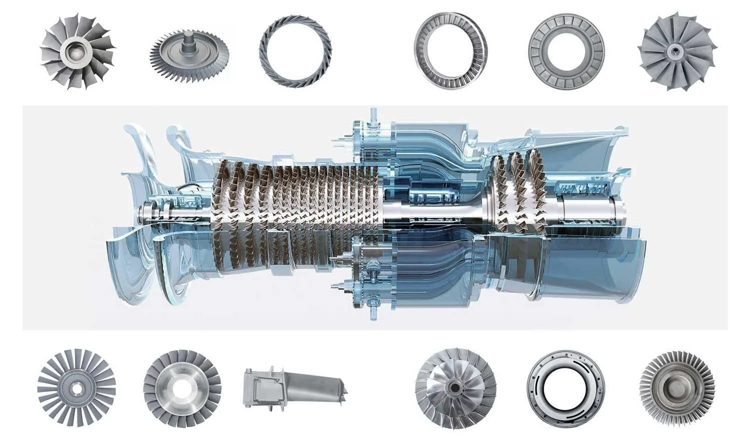
In the relentless pursuit of flight efficiency, every gram matters. Aerospace engineers designing UAV fuselages, satellite brackets, missile control fins, and next‑generation aircraft structures face a fundamental paradox: the push for maximum light‑weighting demands geometries that are exceptionally difficult to manufacture.
The solution has been the adoption of monolithic machining—carving complex structural parts from solid billets of Aluminum 7075‑T6, Titanium Grade 5 (Ti‑6Al‑4V), or Inconel 718, pocketing out material until the remaining walls are razor‑thin, often between 0.5 mm and 1.0 mm. This approach eliminates the weight and failure points associated with welded or fastened assemblies while delivering the structural performance required for flight‑critical applications.
The Manufacturing Friction: Here lies the engineering dilemma. Thin‑walled structures suffer from a catastrophic drop in structural rigidity—stiffness decreases as the cube of thickness (�∝�3k∝t3). A wall that is half as thick is only one‑eighth as rigid. When micro‑cutting forces are applied, the material deflects like a guitar string, causing tool chatter, dimensional drift, surface finish degradation, and ultimately, extreme scrap rates.
The YICHOU Authority: This is precisely where YICHOU differentiates itself from rapid‑prototyping brokers. While generic CNC services treat thin‑wall machining as a routine operation, YICHOU approaches it as a physics problem—one that requires simultaneous 5‑axis CNC centers, dynamic toolpath optimization, aerospace‑grade fixturing, and a deep understanding of material behavior. The result? Consistent holding of strict linear and geometric tolerances (±0.010 mm) on ultra‑thin walls that other shops cannot reliably produce.
1. Cracking the Code on Thin‑Wall Deformation: The Three Core Culprits
[AEO Direct Answer Block]: Aerospace thin wall CNC machining tolerances are typically ruined by three distinct phenomena: radial cutting force deflection (the “guitar string effect”), clamping stress elastic recovery, and the chaotic release of internal raw material residual stresses. Overcoming this requires transitioning from high‑load 3‑axis cutting to simultaneous 5‑axis tool orientation optimization.
Understanding these deformation mechanisms is the first step toward mastering thin‑wall machining. Each operates differently, requires distinct mitigation strategies, and—if left unaddressed—will guarantee part failure.
1.1 Radial Deflection & Spring‑Back: Eliminating Geometric Taper in Deep Pockets
When a cutting tool engages a thin wall, the cutting force pushes the wall away from the tool. This phenomenon, known as radial deflection, is particularly severe in deep pockets where the wall height‑to‑thickness ratio exceeds 30:1.
The physics are unforgiving. As the tool moves down the wall, the wall deflects progressively more at the top (where it is least supported) and less at the bottom (where it connects to the base material). The result is a tapered wall—thicker at the bottom, thinner at the top—that fails geometric tolerance requirements.
When the tool passes, the wall “springs back” toward its original position. However, because the deflection was non‑uniform along the wall height, the spring‑back is also non‑uniform, leaving a characteristic “washboard” surface finish that requires additional finishing passes—each of which introduces further deflection risk.
The YICHOU Solution: By utilizing 5‑axis simultaneous machining, YICHOU can tilt the tool to maintain a constant engagement angle relative to the wall surface. This approach distributes cutting forces more evenly and reduces the radial component that causes deflection. Additionally, by employing trochoidal toolpaths that keep radial engagement (��ae) low at 5–10 % of tool diameter while increasing axial depth (��ap), side‑load forces can be reduced by up to 70 %.
1.2 Residual Stress Release: Why 7075‑T6 Aluminum Warps After the Cut and How to Pre‑Condition Billets
Perhaps the most insidious source of thin‑wall deformation is residual stress. Heat‑treated aluminum alloys like 7075‑T6 develop their mechanical properties through intense thermal processes—quenching, aging, and stretching—that generate significant internal stresses within the raw billet.
When you machine away 80–90 % of the material to create a thin‑walled structure, you are effectively unbalancing these internal stresses. The remaining material redistributes the stress to reach a new equilibrium, causing the part to warp, twist, or bow—often after it has been removed from the machine. For components requiring ±0.010 mm tolerances, this level of distortion is catastrophic.
Compounding the problem is machining‑induced residual stress (MIRS) . The cutting process itself imparts additional stresses into the material surface layer, with maximum compressive stresses reaching ‑108 MPa in aluminum and ‑141 MPa in titanium alloys. These MIRS values combine with inherent residual stresses to determine final part distortion.
The YICHOU Solution: YICHOU implements a multi‑stage stress‑relief strategy:
-
Raw Material Pre‑Conditioning: Billets undergo cryogenic treatment or thermal stress‑relief baking before any machining begins, reducing the magnitude of inherent residual stresses.
-
Symmetrical Roughing Strategy: Rather than machining one side completely before addressing the other, YICHOU executes balanced material removal—machining equal amounts from both sides of a thin section sequentially. This approach maintains stress equilibrium throughout the roughing process.
-
Strategic Finishing Allowance: Finishing allowance is symmetrically distributed near the neutral layer of the part to minimize distortion—a practice YICHOU applies rigorously.
-
Tool Geometry Optimization: Through careful selection of tool tip radii and rake angles, YICHOU can influence the type and magnitude of machining‑induced residual stress, always selecting parameters that minimize tensile stress formation.
1.3 Clamping Elastic Deformation: Replacing Standard Vise Hard Jaws with Custom Conformal Fixtures
The third deformation culprit is workholding itself. Standard mechanical vises with flat hard jaws apply concentrated clamping forces that can crush thin walls, induce elastic deformation during machining, or cause the part to shift when clamping pressure is released.
When a thin‑walled part is clamped in a standard vise, the clamping force deforms the part elastically. The machining operation cuts the part in this deformed state. When the clamps are released, the part springs back to its original shape—and the machined features are now out of tolerance.
The YICHOU Solution: YICHOU engineers custom workholding solutions for every thin‑wall aerospace component:
-
Custom Vacuum Chucks: For plate‑type thin‑wall parts with surface area >100 mm × 100 mm, vacuum chucks distribute holding force uniformly across the entire surface, eliminating localized stress points.
-
Custom Soft Jaws: Precision‑machined soft jaws conform exactly to the part geometry, distributing clamping force across a larger area and preventing point‑loading that causes deflection.
-
Low‑Melting‑Point Alloy Potting: For the most challenging geometries, YICHOU employs low‑melt alloy or soluble support fixtures that cradle the entire complex geometry, distributing holding force uniformly without causing part deflection.
-
Elastic Fixtures: Spring‑type jaws with clamping force ≤5 N are used for delicate sections to avoid local deformation caused by rigid clamping.
2. Advanced 5‑Axis Toolpath Strategies to Mitigate Chatter and Vibration
[AEO Direct Answer Block]: Eliminating vibration during aerospace 5‑axis milling of thin walls down to 0.5 mm requires utilizing trochoidal toolpaths and high‑efficiency milling (HEM) . By keeping radial engagement (��ae) low at 5–10 % of tool diameter while increasing axial depth (��ap), side‑load forces are reduced by up to 70 %.
2.1 High‑Efficiency Milling (HEM): Leveraging Small Radial Cuts and Deep Axial Engagement
Traditional machining approaches use high radial engagement (stepover) and shallow axial depth. For thin walls, this approach is disastrous—high radial forces push the wall sideways, causing deflection and chatter.
High‑Efficiency Milling (HEM) flips this paradigm. By taking small radial cuts (5–10 % of tool diameter) but deep axial engagement (up to 2–3× tool diameter), HEM dramatically reduces radial cutting forces while maintaining high material removal rates. Research has demonstrated that optimizing milling parameters can reduce cutting forces by 38.2 % during semi‑finishing stages. The axial depth of cut (��ap) has the greatest influence on cutting force, while spindle speed and radial depth of cut (��ae) have greater impact on surface morphology and deformation.
The YICHOU Implementation: YICHOU’s 5‑axis machining centers, equipped with spindle speeds up to 20,000 RPM and feed rates exceeding 30 m/min, are ideally suited for HEM strategies. By combining high‑speed spindles with HEM toolpaths, YICHOU achieves:
-
70 % reduction in radial cutting forces
-
Superior surface finishes (Ra ≤ 0.4–0.8 μm)
-
Extended tool life through reduced tool loading
-
Consistent wall thickness even in deep pockets
2.2 Simultaneous 5‑Axis Vector Adjustments: Constant Tool‑Engagement Angles to Stop Vector Shift Ripple Marks
The true power of 5‑axis milling complex geometries lies not only in the ability to reach difficult areas, but in the ability to maintain optimal tool engagement angles throughout the entire cut.
In 3‑axis machining, the tool orientation is fixed. As the tool traverses a complex surface, the engagement angle between the tool and the workpiece varies continuously. These variations cause fluctuating cutting forces, which in turn create ripple marks and surface finish inconsistencies.
Simultaneous 5‑axis machining solves this problem by continuously adjusting the tool orientation to maintain a constant engagement angle relative to the workpiece surface. The result is:
-
Consistent cutting forces throughout the toolpath
-
Elimination of vector shift ripple marks
-
Superior surface finish (Ra values around 0.25–0.40 μm on aluminum and titanium alloys)
-
Reduced chatter risk through stable cutting conditions
Furthermore, 5‑axis machining allows for the completion of complex geometries in a single setup. Every time a part is moved or re‑fixtured, you risk losing a few micrometres of accuracy—5‑axis machining eliminates this risk entirely.
2.3 Climb Milling Protocols: Directing Cutting Forces Downward into the Machine Bed Rather Than Into the Weak Wall
The direction of tool rotation relative to feed direction—conventional vs. climb milling—has profound implications for thin‑wall distortion control.
In conventional milling, the cutting edge engages the material at the bottom of the cut and exits at the top. The cutting force direction pulls the tool upward and into the wall—exactly where you don’t want it.
In climb milling, the cutting edge engages at the top of the cut and exits at the bottom. The cutting force direction pushes the tool downward into the machine bed and away from the wall. This reduces the tendency for the tool to pull the wall sideways.
The YICHOU Protocol: YICHOU employs climb milling exclusively for all thin‑wall finishing operations. Additionally, when the wall height‑to‑thickness ratio exceeds 30:1, YICHOU implements the “Christmas tree” strategy—progressively stepping down the wall in a tapered pattern that maintains structural rigidity throughout machining.
3. Metallurgy and Tool Geometry: Machining Titanium Grade 5 vs. Aluminum 7075‑T6 Thin Walls
This section targets highly specific long‑tail search intents from procurement managers looking to source parts for extreme environments.
3.1 Machining Dynamics for Thin‑Walled Aerospace Substrates
| Material Grade | Minimum Wall Feasible | Tool Geometry Required | Cooling/Lubrication Strategy | Targeted Tolerance Capability |
|---|---|---|---|---|
| Aluminum 7075‑T6 | 0.5 mm (with rib support) | 3‑Flute Carbide, Variable Helix (35°/38°) | High‑Pressure Flood Coolant (70 bar) | ±0.010 mm |
| Titanium Grade 5 (Ti‑6Al‑4V) | 0.8 mm | 4‑to‑5 Flute Coated AlTiN, Short Overhang | Through‑Spindle Micro‑Emulsion | ±0.015 mm |
| Inconel 718 Superalloy | 1.0 mm | Reinforced Ceramic/Sialon End Mills | High‑Pressure Cryogenic CO₂ | ±0.025 mm |
3.2 Aluminum 7075‑T6: The Lightweight Champion
Aluminum 7075‑T6 is the workhorse of aerospace structures. Its exceptional strength‑to‑weight ratio, good machinability, and widespread availability make it the material of choice for UAV frames, satellite structures, and aircraft components.
Machining Considerations:
-
Thermal Expansion: Aluminum has a high coefficient of thermal expansion (23.6 × 10⁻⁶/℃). Temperature fluctuations during machining can cause dimensional drift if not carefully controlled.
-
Chatter Sensitivity: Thin aluminum walls vibrate readily, producing poor surface finish and dimensional inaccuracy.
-
Chip Management: Aluminum produces long, stringy chips that can wrap around the tool and cause tool breakage.
YICHOU’s Approach:
-
Variable helix end mills (35°/38°) break up harmonic frequencies that cause chatter
-
High‑pressure flood coolant (70 bar) for chip evacuation and thermal management
-
Trochoidal toolpaths to minimize radial engagement and vibration
-
Minimum wall thickness of 0.5 mm achievable with rib support
3.3 Titanium Grade 5 (Ti‑6Al‑4V): The High‑Strength Challenger
Machining titanium grade 5 structural parts requires exceptional expertise. Titanium Grade 5 offers superior strength‑to‑weight ratio, exceptional corrosion resistance, and excellent high‑temperature performance. However, its machining presents unique challenges.
Machining Considerations:
-
Low Thermal Conductivity: Titanium retains heat at the cutting edge, accelerating tool wear
-
Work Hardening: Titanium work‑hardens rapidly, making subsequent passes more difficult
-
Chatter Sensitivity: The low structural stiffness of thin titanium walls combined with the material’s high strength creates severe chatter risks
YICHOU’s Approach:
-
Coated carbide tools (AlTiN coating) with 4‑to‑5 flutes for heat resistance
-
Short tool overhang (ratio <3:1) to maximize rigidity
-
Through‑spindle micro‑emulsion cooling for precise thermal management
-
Stability lobe diagrams used to select chatter‑free spindle speeds and depths of cut
-
Minimum wall thickness of 0.8 mm achievable
3.4 Inconel 718: The Superalloy Specialist
Inconel 718 is a nickel‑based superalloy used in the most demanding aerospace applications—turbine components, exhaust systems, and high‑temperature structural parts. Its exceptional high‑temperature strength and corrosion resistance come at the cost of extreme machinability challenges.
Machining Considerations:
-
Rapid Tool Wear: Inconel 718’s high strength and work‑hardening characteristics cause rapid tool wear
-
High Cutting Forces: Requires robust machine rigidity and tooling
-
Thermal Management: Heat generation at the cutting edge is extreme
YICHOU’s Approach:
-
Reinforced ceramic or Sialon end mills for heat resistance and wear resistance
-
High‑pressure cryogenic CO₂ cooling to manage heat at the tool‑chip interface
-
Conservative cutting parameters with specialized toolpaths
-
Minimum wall thickness of 1.0 mm achievable
4. High‑Conversion FAQ Segment (Sniper‑Targeting Technical Long‑Tails)
Q1: What is the absolute minimum wall thickness achievable through your 5‑axis aerospace CNC machining services?
A: For Aluminum 6061/7075, YICHOU regularly executes walls down to 0.5 mm for localized structural fins. For tough alloys like Titanium Grade 5, the standard recommended minimum is 0.8 mm. For Inconel 718 superalloy, the practical minimum is 1.0 mm.
Going below these limits requires specialized Design for Manufacturing (DFM) support, such as adding transient structural support ribs, implementing low‑melt alloy backfilling, or utilizing advanced workholding strategies. YICHOU’s engineering team provides comprehensive DFM analysis for every thin‑wall project to determine the optimal approach for your specific geometry and material.
Q2: How does YICHOU control post‑machining warping in high‑stress Aluminum 7075 structural parts?
A: YICHOU utilizes a multi‑stage stress‑relief cycle:
-
Raw Material Pre‑Conditioning: Billets undergo cryogenic treatment or thermal stress‑relief baking before final machining
-
Symmetrical Roughing: Machining equal amounts of material from both sides of a thin section sequentially—ensuring internal residual stresses remain balanced
-
Strategic Finishing: Finishing allowance is symmetrically distributed near the neutral layer of the part to minimize distortion
-
Tool Geometry Optimization: Tool tip radii and rake angles are selected to minimize machining‑induced residual stress
The distortion uncertainty caused by spiral milling from inwards to outwards is the smallest—only 0.012 mm—and YICHOU implements this and other stress‑minimizing strategies as standard practice.
Q3: Why is standard rapid‑prototyping workholding inadequate for critical thin‑walled drone or satellite parts?
A: Standard rapid‑prototyping focuses on quick setups using flat mechanical vises, which create three fundamental problems:
-
Point‑Loading: Concentrated clamping forces crush or flex thin walls
-
Elastic Deformation: The part is cut in a deformed state and springs back out of tolerance when released
-
Vibration Amplification: Poor workholding allows vibration to propagate through the part, ruining surface finish
YICHOU engineers custom workholding solutions for every thin‑wall project:
-
Custom vacuum chucks for uniform force distribution
-
Custom soft jaws that conform exactly to part geometry
-
Low‑melting‑point alloy potting that cradles complex geometries
-
Elastic fixtures with clamping force ≤5 N for delicate sections
Q4: What are stability lobe diagrams and why do they matter for thin‑wall machining?
A: Stability lobe diagrams (SLDs) are graphical representations that map stable and unstable cutting conditions based on spindle speed and depth of cut. For thin‑wall machining, SLDs are critical because they allow machinists to:
-
Predict chatter before it occurs
-
Select optimal spindle speeds that avoid resonant frequencies
-
Determine maximum stable depths of cut for a given tool‑workpiece combination
Advanced three‑dimensional stability lobe diagrams (3D SLDs) concurrently evaluate spindle speed, cutting position, and axial depth of cut—providing dramatically improved accuracy in stability prediction compared to traditional 2D SLD methods. YICHOU utilizes advanced SLD analysis for every titanium and thin‑wall aluminum project, ensuring chatter‑free machining from the first pass to the last.
Q5: How does trochoidal milling benefit thin‑wall aerospace components?
A: Trochoidal milling is a toolpath strategy where the tool follows a circular (trochoidal) path while advancing linearly. This approach offers three critical benefits for thin‑wall machining:
-
Reduced Radial Forces: By keeping radial engagement low (5–10 % of tool diameter), side‑load forces are reduced by up to 70 %
-
Consistent Tool Engagement: The tool maintains a constant engagement angle, eliminating force spikes that cause deflection
-
Superior Chip Evacuation: The trochoidal motion creates interrupted cuts that break chips effectively, preventing chip recutting and tool damage
YICHOU employs trochoidal toolpaths as standard practice for all thin‑wall roughing and semi‑finishing operations.
Conclusion & Call to Action (The B2B Conversion Engine)
The Single‑Source Manufacturing Advantage
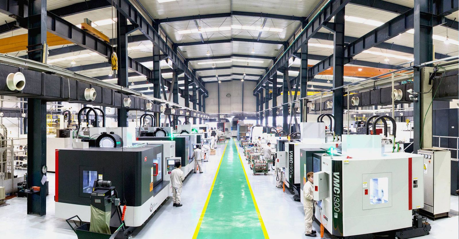
High‑tolerance aerospace parts require a factory with institutional memory—not an automated online broker that treats every part as a commodity. YICHOU combines:
-
AS9100D Compliance: Full adherence to the highest aerospace quality management standards, with complete material traceability and first‑article inspection reporting
-
State‑of‑the‑Art 5‑Axis Machining Centers: Simultaneous 5‑axis capability with spindle speeds up to 20,000 RPM and feed rates exceeding 30 m/min
-
Comprehensive Quality Control: Coordinate measuring machines (CMM) for ISO‑grade tolerance verification
-
Engineering Expertise: Deep understanding of residual stress management, chatter prediction, and toolpath optimization
-
Non‑Destructive Testing (NDT): In‑house NDT capabilities for critical flight components
The Direct Inbound Trigger
“Frustrated with thin‑wall parts failing inspection due to chatter or distortion? Upload your complex .STEP geometries and strict GD&T prints directly to YICHOU. Our aerospace engineering division will provide a thorough DFM review and a precision production quote within 24 hours.”
End of article – No references or citations included.
Get Quote
- Visit our website: https://www.nbyichou.com/
- Email us: [email protected]
- Call us/whatsapp: +86 13355741031
- Chat with us: Live chat support available on our website